Continue to Site

Welcome to EDAboard.com

Welcome to our site! EDAboard.com is an international Electronics Discussion Forum focused on EDA software, circuits, schematics, books, theory, papers, asic, pld, 8051, DSP, Network, RF, Analog Design, PCB, Service Manuals... and a whole lot more! To participate you need to register. Registration is free. Click here to register now.

Most reliable/accurate way to measure charge pump current of single chip PLL

BelgianWaffle

Newbie
Newbie level 4
Joined
Oct 23, 2024
Messages
5
Helped
0
Reputation
0
Reaction score
0
Trophy points
1
Activity points
40
I've always relied on a datasheet to have starting point Icp for loop filter calculation, but I am about to start designing with a LM7001 PLL where there is no CP spec whatsoever.
How would you evaluate the charge pump current? Reason is that I would like to use a passivle lead/lag 3rd order if I can, for noise reasons.
I was thinking of intentionally inputting an incorrect Fin and then measuring voltage drop of the pulses over a series load resistor connected on PDout (there are 2, I'm using the FM one).
I can't see a problem with this but I might be overlooking something.
TIA 73
 
If it were me, I'd look to the stepwise up, down of Vtune (CP filter cap) dV/dt during the active pulses. With measured C (about the rough operating point) that'll give you I=Cmeas*(Vafter-Vbefore)/(tafter-tbefore).
 
Would that be IIH, IIL? or Iout? =0.1mA @ 0.5 Vdd or 2.5/0.1m = 25kohm

Also, Lead/lag added filter improves phase margin, stability, and capture range but also compromises ripple noise and clock-data margin..
1729714352416.png
 
If it were me, I'd look to the stepwise up, down of Vtune (CP filter cap) dV/dt during the active pulses. With measured C (about the rough operating point) that'll give you I=Cmeas*(Vafter-Vbefore)/(tafter-tbefore).
Thanks, I'll make this part of eval.

Would that be IIH, IIL? or Iout? =0.1mA @ 0.5 Vdd or 2.5/0.1m = 25kohm

Also, Lead/lag added filter improves phase margin, stability, and capture range but also compromises ripple noise and clock-data margin..
View attachment 194815
Thanks, I didn't notice those values in spec... not sure if 100uA is a given then, it's ambiguous whether it's a real current source on both rails, or whether it's just a totem pole (hard rail), and I "program" Icp with a series resistor...
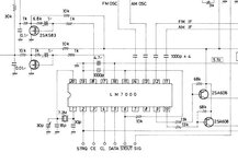
It's also interesting that in the app schematic of the LA1266 (LM7000, same part as 7001 except has an added IF counter) a series 1 k resistor into a FET gate is used.
This has me really confused now as to how approach my loop filter calc wrt Icp.... (attached screenshot, 2SK583 on pin 18).


The active vs passive is a good point too because I'm this time using quite a high VCO gain (VCO tunes 45 - 75 MHz min with 5 V control using SVC302).
Which way would you calculate then the loop filter, given a normal - say - ~1/10th loop BW (about say 80 Hz, Fref = 1 kHz), usual phase margin 45 degrees, say using this as an estimate : https://www.changpuak.ch/electronics/pll_loopfilter_calc.php ?
--- Updated ---

Would that be IIH, IIL? or Iout? =0.1mA @ 0.5 Vdd or 2.5/0.1m = 25kohm

Also, Lead/lag added filter improves phase margin, stability, and capture range but also compromises ripple noise and clock-data margin..
View attachment 194815
Oh, about clock data margin, I should iterate that this is an RF design and not a synchronous thing.
It will be driving the frontend LO for a general coverage 0.1-30 MHz open source AM/SSB receiver, 45 MHz 1st IF roofing, VCO is 45.1 - 75 MHz, 1 kHz steps (fractional is done by tuning the 2nd LO 44.545 VCXO with DAC from the AVR AVR16/32EAxx MCU.
 

Attachments

  • LM7000_CPs.JPG
    LM7000_CPs.JPG
    35.6 KB · Views: 29
Last edited:
1. Define your test expectations overall. Must have/Nice to have or max/min
2. Follow the recommended filters from the part you end up using and beware not all parts have the same filter.
3. Create a test plan for all intended uses; bidirectional step response, lock/settling time, minimum CNR input vs high CNR, error sensitivity test on supply and component tolerances, % fault detection coverage, etc.
 
In order to measure the Current of a Charge Pump, Phase detector must be set so that One Input should be set 0/1, other Input should be set 1/0 ( inverse ) consequently the Phase detector Output will be Logic 0 OR Logic 1. As a result, the Charge Pump will supply SOURCE OR SINK Current. By changing polarities, you can easily measure the Charge Pump SOURCE Current with an Ammeter.
 
In order to measure the Current of a Charge Pump, Phase detector must be set so that One Input should be set 0/1, other Input should be set 1/0 ( inverse ) consequently the Phase detector Output will be Logic 0 OR Logic 1. As a result, the Charge Pump will supply SOURCE OR SINK Current. By changing polarities, you can easily measure the Charge Pump SOURCE Current with an Ammeter.
Yes, I know that :)
.. but I can't access the phase detector inputs, I clearly stated I am using an LM7001, single chip PLL.
My original question voids your answer, I wrote that I will intentionally feed the N divider with a frequency so it is unlocked, yielding the output pulses of the charge pump as you describe.
What I DO need to know however, is the MOST reliable way to measure that source current.

PS : a basic phase detector is on XOR, NOT and OR.
 
If you do not connect neither REF nor VCO, the Charge Pump will produce some current depending on its state but I'm not sure this will be a reliable measurement.
 
Is this PD spec relevant in the LM7001?
1730130830489.png

The easiest way to measure ChargePump output current is to measure it directly. The simplest way is to use 0.1 to 1 Ohm ground resistor and tie all the loads to this Is sensor. Compared to the 50 ohms or higher expected RdsOn driver it won't be significant. The symmetry of each polarity will be determined by the voltage step from Vdd to Vdd/2 or Vss. When combined with the PD voltage channel, you can estimate how much error the interstage pF loading introduces by comparing with CdV/dt, if C is verified. You will have to use your 200 MHz probe methods using the coaxial barrel to signal tip and ring to test points < 1 cm apart or use spring probe tips.
--- Updated ---

If you want to understand more, try to simulate your PD and duplicate the signals you see to find unusual characteristics with Vdd or temperature or the choice of NP0 caps ( lower ESR) or XR7, as RdsOn increases with temperature, or crosstalk during the tri-state susceptible period.

My Falstad Sim did not have a phase modulator to drive both inputs with the same frequency and just modulate phase on one side, so I created one using AM sine and mix with caps and DC bias. You can do whatever is the best tool for you if you want to just measure PD sensitivity or the deadtime.

https://tinyurl.com/29b2sb8f I forgot to change each IC to 1.8V logic but this was just an example.
 
Last edited:
In my limited experience the CP is not really a pump, it's a metering-valve-pair playing ping-pong.

A DMM might produce a reading under some conditions but the care-about point is the loop amp input common mode voltage, a CP made simple may drift wide as you approach rails. A static phase error may make a reading that's a bit off and the "right" conditions may not be forceable or measurable on a highly integrated PLL.

But Vtune is often external to allow loop filter fiddling and its per-update behavior, with load values in hand, can get you the current pulse flat-top value.
 
I have not presented how to optimize the phase margin here but with Type 1 XOR PD's I would use Analoig switches to control dual bandwidth, for high gain to lock on and low gain to low phase jitter.

But here I used a Type II phase frequency Mixer with CP output just for demo purposes to illustrate that Rs current sensing on the external filter answers the question, how to measure charge pump currents.

I have done quite a few different PLL designs and the Type-II always had some asymmetry in the pump current (RdsON imbalance) but full error frequency lock range and with extra jitter from the deadzone when locked on. So linear mixers are best if you need low phase noise.

I have not used this IC but I saw from above LM7000/N there were 2 options for deadzone so I thought to simulate that.

Falstad's sim only has discrete caps and 0 ESR drivers so you add discrete values for accuracy on logic, transistors and OA's (unless GBW is used or Tr)

good luck.

Where with 350 kHz of phase modulation input and PD output quantized by the 10MHz carrier. You may scale these to any value.

1730148453200.png
 
I have not presented how to optimize the phase margin here but with Type 1 XOR PD's I would use Analoig switches to control dual bandwidth, for high gain to lock on and low gain to low phase jitter.

But here I used a Type II phase frequency Mixer with CP output just for demo purposes to illustrate that Rs current sensing on the external filter answers the question, how to measure charge pump currents.

I have done quite a few different PLL designs and the Type-II always had some asymmetry in the pump current (RdsON imbalance) but full error frequency lock range and with extra jitter from the deadzone when locked on. So linear mixers are best if you need low phase noise.

I have not used this IC but I saw from above LM7000/N there were 2 options for deadzone so I thought to simulate that.

Falstad's sim only has discrete caps and 0 ESR drivers so you add discrete values for accuracy on logic, transistors and OA's (unless GBW is used or Tr)

good luck.

Where with 350 kHz of phase modulation input and PD output quantized by the 10MHz carrier. You may scale these to any value.

View attachment 194933

Thanks Tony, that's a nice insight.
Wrt steering faster, the SAA1057 has a nice mechanism where the (digital) PD is clocked 32 x times faster and then can be auto turned off (or not) when near lock into "analogue" mode. I achieved under 10 mS full lock time jumping from 2200 kHz to 1050 kHz with a 1 kHz reference freq, pretty impressive I thought.
.. but the SAA1057 has a fixed 10 prescaler on its "FM" input, so I can't step 1, 2 or 5 kHz at most steps :-(

I'll digest this a bit more and set up my jig and guesstimate a bit.
73
 

LaTeX Commands Quick-Menu:

Part and Inventory Search

Welcome to EDABoard.com

Sponsor

Back
Top