Continue to Site

Welcome to EDAboard.com

Welcome to our site! EDAboard.com is an international Electronics Discussion Forum focused on EDA software, circuits, schematics, books, theory, papers, asic, pld, 8051, DSP, Network, RF, Analog Design, PCB, Service Manuals... and a whole lot more! To participate you need to register. Registration is free. Click here to register now.

Mosfet Ultrasonic Power Amplifier

Status
Not open for further replies.

MexicoMac

Newbie level 2
Newbie level 2
Joined
Sep 29, 2013
Messages
2
Helped
0
Reputation
0
Reaction score
0
Trophy points
1
Activity points
16
I am looking for a circuit diagram for a high power ultrasonic amplifier. Needs to drive an underwater transducer rated at 50 watts. Currently using a single Hfet driving a 1:25 toroid to 1000vpp, but I need to increase the duty cycle past 1% for more output power. I think a dual HFet design with a dual DC power supply would work best.
Any ideas would be appreciated.
Thanks,
Mac
 

what are the specs of your transducer ? I.e. its frequency, capacitance, etc ?

Your proposed circuit might just the the right solution, so why don't you post your circuit...
Note that driving the typical ultrasonic transducer is equivalent to driving a capacitive speaker, and there are plenty of circuits available for that. Different frequency range though.
 

I think you can refer this -

**broken link removed**

Good Luck
 

There is much literature around which has a lot of theoretical analysis done by PhD or MTech aspirants. None of them address practical designs.... all of them have a huge number of undecipherable equations involving integrals, differentials, tensor analysis, bode plots, blah blah. I suspect that none of these academics has actually built an ultrasonic transducer high power driver/ amplifier. Okay... maybe 1 or 2 have.

Don't waste your time with that claptrap.
 

The 1000V is just there to drive current into capacitive load. What frequency (s?) are you wanting to use this kit at, because the cheapest bang for your bucks is to match the capacitive impedance out with a series inductor,likewise to resonate the connecting leads out with an inductor across the transducer itself.
Do some experimenting with a low level signals to build a reasonable equivalent circuit of your transducer, then a matching circuit. To deliver a lot of power it is convenient for the matched impedance to be in the order of 10-100 ohms. Beyond these limits you have to either generate excessive voltage or current.
Frank
 

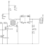
Here is the circuit I am using. New_Option_TX.png
 

What do you think the diodes are for?
Apparently it's a sonar output stage, the diodes are there to isolate the receive channel (not shown in the schematic) from the transducer. Without a receive channel, the diodes are useless.

Regarding "more output power", you should check if the transducer can tolerate a higher drive voltage without damage (mechanical break or piezo depolarization).
 

Status
Not open for further replies.

Part and Inventory Search

Welcome to EDABoard.com

Sponsor

Back
Top