DM0119
Newbie
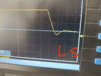
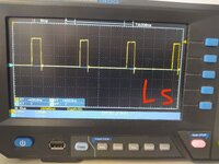
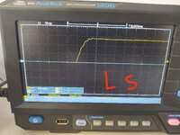
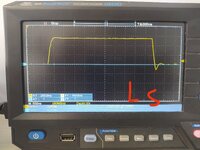
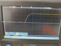
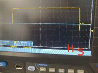
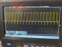
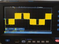
After a look in deep in the attached photos the switching curves of the gates,and i am wondering if this switching is acceptable for work MOSFET in spwm H bridge LF inverter.I would like your general opinion on all points and your suggestion for some improvement.
Details for the system:
.Dead time at 1 μs for test reasons
.Driver IC ir2113s
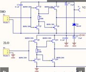
.Totem pole gate driver amplifier 7 amps with mosfet.(Attached photo)
.Power mosfets FDH055N15A (6 in parallel)
.Rg is 6.8 ohm (for each mosfet)
.Rgs is 33 kohm ( for each mosfet)
.I use antiparallel diodes for each.
Thank you in advance !
Details for the system:
.Dead time at 1 μs for test reasons
.Driver IC ir2113s
.Totem pole gate driver amplifier 7 amps with mosfet.(Attached photo)
.Power mosfets FDH055N15A (6 in parallel)
.Rg is 6.8 ohm (for each mosfet)
.Rgs is 33 kohm ( for each mosfet)
.I use antiparallel diodes for each.
Thank you in advance !
Attachments
-
 IMG_20240705_005319.jpg3.7 MB · Views: 20
 -
 IMG_20240705_005130.jpg4.1 MB · Views: 16
 -
 IMG_20240705_005110.jpg4.4 MB · Views: 18
 -
 IMG_20240705_005050.jpg4 MB · Views: 19
 -
 IMG_20240705_004956.jpg4.8 MB · Views: 18
 -
 IMG_20240705_004902.jpg4.4 MB · Views: 19
 -
 IMG_20240705_004831.jpg4.7 MB · Views: 18
 -
 IMG_20240705_004831.jpg4.7 MB · Views: 17
 -
 IMG_20240704_125647.jpg2.9 MB · Views: 20
 -
 IMG_20240705_014619.jpg144.8 KB · Views: 18