yassin.kraouch
Advanced Member level 2

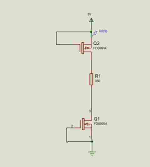
i use this MOSFET https://www.fairchildsemi.com/ds/FD/FDS9934C.pdf
the schematic is
the gate of the PMOS is connected to Vcc and the gate of the NMOS is connected to GND, the problem that i found there is a current that pass throught R1, have you an idea about this problem ?
the schematic is

the gate of the PMOS is connected to Vcc and the gate of the NMOS is connected to GND, the problem that i found there is a current that pass throught R1, have you an idea about this problem ?