Continue to Site

Welcome to EDAboard.com

Welcome to our site! EDAboard.com is an international Electronics Discussion Forum focused on EDA software, circuits, schematics, books, theory, papers, asic, pld, 8051, DSP, Network, RF, Analog Design, PCB, Service Manuals... and a whole lot more! To participate you need to register. Registration is free. Click here to register now.

MOSFET Gate starts to oscillate at Miller Plateau.

vignesh4488

Newbie
Newbie level 2
Joined
Jan 29, 2025
Messages
2
Helped
0
Reputation
0
Reaction score
0
Trophy points
1
Activity points
22
Hi,

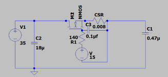
My circuit is actually used for current sensing. I have provided the overall circuit for reference.

I am facing a gate oscillation issue at 24Mhz when the MOSFET begins to conduct at threshold.

I have attached the waveform and schematic for your reference.

Green -Gate Of MOSFET Orange- Vds

MOSFET used: UF3SC120040B7S
Input voltage: 35V

Please provide your suggestions regarding the above problem.

Regards,

Vignesh.

Circuit.png


1738174193749.jpg

1738174614169.jpg
 

Attachments

  • Circuit.png
    Circuit.png
    51 KB · Views: 36
Hi,

the schematic may be from a simulation ... I don´t expect it to oscillate.
I rather expect the real circuit to oscillate.
--> Please calrify.

If so, I xpect a bad PCB layout / bad wiring / bad part selection to be the root cuase for the oscillation.

Klaus
 
Hi,

I have probed gate and drain of MOSFET.

Layout: Source of MOSFET is routed longer followed by one 0.47uF capacitor.

Actual my circuit is to work on 350V. When I have turned on MOSFET with 350V, D-S are shorted.

So, I have started debugging with 35Vdc but still oscillation in D-S and G-S.

I have also gone through some research paper on online they have mentioned oscillation because of source inductance. In CSR has inductance of 5nH therefore I have shorted that tested and same problem exists.

Another one question, How to calculate PCB trace inductance and any idea on that?

Regards,
Vignesh.
 
1nH/mm is roughly right but coupling is anyone's guess. And that's the big deal, where is your feedback, your gain and your phase shift? About the only a priori "knowns" are rough Cgx and rough gain vs OP for one path.
 
Layout: Source of MOSFET is routed longer followed by one 0.47uF capacitor.
you already posted megabytes of scope pictures ... why not a photo of your circuit - including the scope connections? (100kBytes should be sufficient.)

Klaus


Write your reply...

LaTeX Commands Quick-Menu:

Part and Inventory Search

Welcome to EDABoard.com

Sponsor

Back
Top