Continue to Site

Welcome to EDAboard.com

Welcome to our site! EDAboard.com is an international Electronics Discussion Forum focused on EDA software, circuits, schematics, books, theory, papers, asic, pld, 8051, DSP, Network, RF, Analog Design, PCB, Service Manuals... and a whole lot more! To participate you need to register. Registration is free. Click here to register now.

mosfet drive bridge --> DC motor/fan ..need help

Status
Not open for further replies.

tuk

Junior Member level 1
Joined
Jun 19, 2011
Messages
18
Helped
0
Reputation
0
Reaction score
0
Trophy points
1,281
Activity points
1,478
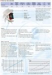
fan/motor details
DC FAN INFO.JPG

as the title suggests I am planning on using a mosfet driver to control a dc fan/motor, have no idea what kind I need to do the job, there are many different types

fan/motor will run 24/7 365 days ..possibly for several years
fan/motor will run continuously and vary between 10%-100% power
fan/motor speed will be auto controlled by an MC(Arduino/PWM) via the mosfet ......in response to temperature
if the mosfet can feedback motor info to the MC ...speed etc that would good also

1)how to choose a suitable driver: do I match the current rating of mosfet to the fan/motor current rating?
2)can I buy something off the shelf or do I have to build?
3)how exactly does the mosfet connect to the fan/motor ..is the fans power cable run through the mosfet or do I need to open up the fan housing and connect directly to the motor?
4)Are there any extra fire risks or other safety issues I have to consider?
 
Last edited:

Do not install any motor drivers, you destroy that motor.

I look at............

**broken link removed**

and there is written ............

TD-800/200 ECOWATT

Motoren
– EC-Motoren elektronisch kommutiert
– Spannungsversorgung 230V, 50/60 Hz
– Schutzart IP 44
– Isolierstoffklasse B
– Motorbemessung Dauerbetrieb S1
– Integrierte Steuerungselektronik
– Integrierter Steuerpotentiometer
– Signaleingang 0–10 V DC
– Ausgang 10 V DC
– Ausgang 24 V DC
– Geschlossene Kugellager – wartungsfrei

so there is allready motor controller and power supply for 10Vdc
you should only need a potentiometer.
( I guess 5...10kohms)

Look inside motor connection box.

Regards KAK
 
Last edited:
  • Like
Reactions: tuk

    tuk

    Points: 2
    Helpful Answer Positive Rating
engines
- Electronically commutated EC motors
- Power supply 230V, 50/60 Hz
- Protection class IP 44
- Insulation class B
- Rated motor continuous operation S1
- Integrated control electronics
- Integrated control potentiometer

- Signal input 0-10 V DC
- Output 10 V DC
- Output 24 V DC
- Closed ball bearings - maintenance-free

Thanks kak,

I can't look inside as I haven't bought the fan yet, & the information doesn't seem to be available in English, it says in bold the controller + potentiometer are integrated but looking at the table in your link it says the controller is a REB-ECOWATT ...which is an external controller ..so I'm a little confused..

does the REB-ECOWATT connect to the Integrated/internal potentiometer inside the motor connection box .. & are you saying I need to use an external potentiometer(5...10kohms) to control the potentiometer inside the motor connection box? .. basically the REB-ECOWAT is a potentiometer?

sry for noob questions
 
Last edited:

ecowatt wiring schematic.jpg
ahh I'v just noticed the wiring schematic for the REB-ECOWATT(external speed adjuster) wiring to the fan, from looking at the schematic the speed can be adjusted manually with screwdriver or remotely with the REB-ECOWATT

so bearing in mind I want to use my own micro-controller(Arduino) ...to adjust the fan speed to any setting in the range 10-100% ..how do I find out the type of input signal that changes the fan speed ...just like the REB-ECOWAT can do

REB-ECOWAT

Remote setpoint adjuster for brushless DC motors and
Frequency.
- Surface Mounting
- Protection class II
- 10 V DC input
- 0-10 V DC output
- Potential-free auxiliary contact
dimensions
80 mm D = 68 mm
 
Last edited:

One more time........................

**broken link removed**
-wiring diagram for 2-speed ( here said that standard model is 2-speed)

for ecowatt model said - Electronics totally integrated in the product
**broken link removed**

here is REB-Ecowatt pot.meter
**broken link removed**

here is the wiring schema for TD Ecowatt 800/200
--look page 72
http://pdfs.findtheneedle.co.uk/7503-domcom-pp34-72.pdf

I hope this helps you.

KAK
 
  • Like
Reactions: tuk

    tuk

    Points: 2
    Helpful Answer Positive Rating
I see two main ways to do this control system with arduino

1. Arduino outputs 0...10V to connections Vin --GND in blower.
**broken link removed**

2. Arduino commands small servo to turn external pot.meter.
**broken link removed**

KAK
 
Last edited:
  • Like
Reactions: tuk

    tuk

    Points: 2
    Helpful Answer Positive Rating
interesting.. I like the idea of amplifying the pwm outputs(0-5v) to (0-10v) to get the necessary range

I'v just been reading about digipots **broken link removed** SPI is compatible with Arduino

the AD5206 Digital Potentiometer in the example(click the green above) is only 5v, but I found this one

AD3376
128 positions
10 kΩ, 50 kΩ, 100 kΩ
20 V to 30 V single-supply operation
±10 V to ±15 V dual-supply operation
3-wire SPI®-compatible serial interface
THD 0.006% typical
Programmable preset
Power shutdown: less than 1 μA
iCMOS™ process technology

LINK

or should I be looking for a maximum of 10v only

also this one which has 256 positions...that means a potential 256 speed/volt settings for the fan right or?
AD5290
256 position
10 kΩ, 50 kΩ, 100 kΩ
+20 V to +30 V single-supply operation
±10 V to ±15 V dual-supply operation
3-wire SPI®-compatible serial interface
Low temperature coefficient 35 ppm/o
C typical
THD 0.006% typical
Midscale preset
Compact MSOP-10 package
Automotive temperature range: −40C to +125

LINK

I notice on the fan there is also a 25v/dc input as well as the 10v option ...what is the purpose of the 25v input ..does the higher voltage allow a wider range? or something else
 

Yes for example Maxim and Analog Devices produce digital potentiometers with SPI or I2C bus
If you like to use those, announce that they need buffer amplifier for protection and current amplification.
Pot.meter like those can handle only very small currents ( check from datasheet )

Dataheets here............

Digital Potentiometers | Digital to Analog Converters | Analog Devices

I think in this case 15V type or higher is right choice, and because it needs amplifier maybe 50 or 100kohms is right resistance value.

You can use blower 10V output I guess (again) it can source 1...2mA or
take control 0...10V from Arduinos power supply.

Not wise to connect anything to 24Vdc output, until you know what is the meaning for it.

KAK

Ps. Here is discussion about MCU D/A conversion .
https://www.edaboard.com/threads/214467/

KAK
 
Last edited:
  • Like
Reactions: tuk

    tuk

    Points: 2
    Helpful Answer Positive Rating
Thanks for all your help and guidance yesterday Kak , much appreciated

I am thinking of going with your schematic from that thread
28_1307026226.jpg

..also looking at **broken link removed** ..the kind you build yourself ..could be useful for testing outputs etc on vera board, before committing to solder ..do you think or waste of money?
 

Thats Ok.
If you need help, just ask, I will try............

About oscilloscope , if you think thatkind device is useful , Ok , at least it is one of cheapest ones.

I myself use PC-USB scope and an old 40Mhz classic device.

It´s wise the test and measure new circuits someway , like connect circuit first in test board.

Then there is simulation programs, you dont even need real components for testing circuits.
I use Tina-TI for that.

Look in my group post ...............


KAK
 

Status
Not open for further replies.

Part and Inventory Search

Welcome to EDABoard.com

Sponsor

Back
Top