Continue to Site

Welcome to EDAboard.com

Welcome to our site! EDAboard.com is an international Electronics Discussion Forum focused on EDA software, circuits, schematics, books, theory, papers, asic, pld, 8051, DSP, Network, RF, Analog Design, PCB, Service Manuals... and a whole lot more! To participate you need to register. Registration is free. Click here to register now.

MOSFET design for power supply control

Status
Not open for further replies.

OradFarez

Member level 1
Member level 1
Joined
Feb 9, 2007
Messages
40
Helped
1
Reputation
2
Reaction score
0
Trophy points
1,286
Activity points
1,583
Hello. I usually do digital design but I need to make a MOSFET circuit that enables a power supply to drive a load or be removed. This is so that I can have one supply active only when another one is already on.

I have a 2.8V supply (VIOHI) and a 3.3V supply (3.3V_RAW) as shown in the picture below. The load is attached to the 3.3V net:
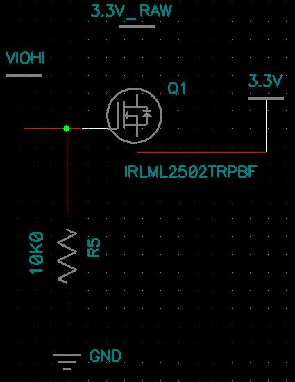
15_1181153177.jpg


I have seen N-Channel MOSFETs used to sink a power source to ground and the positive end of the load is always connected but I want the opposite. Will this circuit work? Is there a better way?


Thank you!
 

is your load pure resistive or it also include inductive one?
 

Well, the main problem with the above circuit is you are using N-Channel MOSFET. You need Vgs higher then Vth (data sheet shows .6 - 1.2 V), so your 3.3V rail can be as low as 2.8V - 1.2V = 1.6V.

If your VIOHI domain was a higher voltage than 3.3V by at leat the Vth, you can use your circuit.


Use a PMOS mosfet instead with resitor connected to VIOHI and gate tied to gnd.

EDIT: Oops... you want to make sure the 3.3 domain is power down until the power on the 2.8 domain is fully on.... how about a resistor between the VIOHI and gate of PMOS with output of a inverter or some logic driving the gate node low when you want 3.3V domain on. You could tie the input of the inverter high so that the 3.3V domain turns on after 2.8V domain power up enough to trip the nmos in the inverter.
 

    OradFarez

    Points: 2
    Helpful Answer Positive Rating
Thanks for the reply. I understand what you are saying. The N-Channel is a bad idea in this application. I know of circuits that use the inverted method you speak of and so I think I will just switch it to that design. I wanted as few parts as possible but it looks like just a MOSFET won't do.


Thanks for your help!
 

OradFarez said:
Hello. I usually do digital design but I need to make a MOSFET circuit that enables a power supply to drive a load or be removed. This is so that I can have one supply active only when another one is already on.

I have a 2.8V supply (VIOHI) and a 3.3V supply (3.3V_RAW) as shown in the picture below. The load is attached to the 3.3V net:
15_1181153177.jpg


I have seen N-Channel MOSFETs used to sink a power source to ground and the positive end of the load is always connected but I want the opposite. Will this circuit work? Is there a better way?


Thank you!

What's the purpose of your design? I see that the 3.3V will cutoff/turnoff if your voltage 2.8V voltage at the gate will cutoff.

What do you mean by "you want the opposite?" Did you mean you want to use P-type instead of N-type?
 

Hello. I am creating a design with two very separate power supplies on two separate boards. One of them has power management from a dev kit and the other (mine) needs to be managed. I don't want my board to be powered when the other one is not so I want to gate the power to MY board by only coming up when it "senses" power from the dev kit (which has software controlled power buttons, sleep modes, etc.).

This is what I meant by the opposite: NORMALLY OFF and only ON when VIOHI is applied. Are you saying that the circuit I show would work as is?


Thanks!
 

Status
Not open for further replies.

Similar threads

Part and Inventory Search

Welcome to EDABoard.com

Sponsor

Back
Top