Continue to Site

Welcome to EDAboard.com

Welcome to our site! EDAboard.com is an international Electronics Discussion Forum focused on EDA software, circuits, schematics, books, theory, papers, asic, pld, 8051, DSP, Network, RF, Analog Design, PCB, Service Manuals... and a whole lot more! To participate you need to register. Registration is free. Click here to register now.

Minimum load current of LDO?

Status
Not open for further replies.
T

treez

Guest
Newbie level 1
Hello,

I wish to use the MCP1703 voltage regulator to produce a 3V reference voltage from a 3.3V rail.
(it will provide the reference voltage for a microcontrollers ADC reference input)
What is the minimum load current that i need to load the output with in order to get the output voltage accurate at 3V?
The datasheet graphs seem to show a minimum current of 1mA flowing.
What will the accuracy be like if only 100uA flows?

MCP1703 datasheet
https://ww1.microchip.com/downloads/en/DeviceDoc/22049f.pdf
 

The datasheet graphs seem to show a minimum current of 1mA flowing.
Some, not all.

What will the accuracy be like if only 100uA flows?
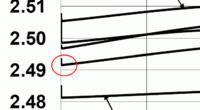
The question can't be answered by a specification. Decide yourself if the exact course of the curves in Figure 2-11 has a meaning.
I fear, it might.
 
  • Like
Reactions: treez

    T

    Points: 2
    Helpful Answer Positive Rating
The big pass device will leak, and that leakage has to go
somewhere or the output will go out of regulation, high.
This current can be taken up by the feedback network if
low enough impedance. Some LDOs have a sort of class AB
output with a sink device (helps also with low-load transient
response, keeping the "load pole" under control) and these
would have no minimum load because they provide it.
 
  • Like
Reactions: treez

    T

    Points: 2
    Helpful Answer Positive Rating
i'd say fig 2-11 indicates excellent load regulation at 0mA load...looks liek it to me
 

well spotted, i see what you mean, but those blips dont exactly extend a long way off the regulation voltage...........i am not sure if there is some intended extrapolation.
Its just disappointing that the datasheet has not doen anything to tell of the performance on absolutely no load, or given a minimum load. The sheet says it can be used as a reference , but then neglects to tell
 

I imagine, that the "blips" might show leakage current of the the series pass transistor. As you find out yourself, there's no accuracy specification for Iout=0, which contradicts somehow the suggested usage as voltage reference. Of course you can't read quantitative specifications into some flyspeck on a diagram, not even the existence of these blips.

What I would do is to provide an optional load resistor in the circuit and find out empirically if it's actually required, including tests over the full temperature range.
 

Status
Not open for further replies.

Similar threads

Part and Inventory Search

Welcome to EDABoard.com

Sponsor

Back
Top