bmandl
Full Member level 4

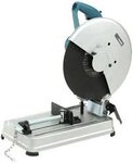
Hello guys. Few days ago, I started my first electronic enclosure design for 3d printing. I have never tried to design one before and I got so exited, that I ordered my own 3d printer  Now, since I will have a chance to print my own models, I was thinking that I could make something useful. So I came to an idea, what if I build my own miniature table saw for pcb cutting. I always have problems with cutting pcbs, because I don't have the tool for it. I will design a 3d modular design, but I won't print everything. I will CNC mill the frame, which will hold everything together. I have one working coffee grinder electric motor, which I will use for turning blade (probably 2" or 4" blade). Now, this motor will be fixed on a bracket. For better understanding, I will try to do something like this:
**broken link removed**.
Of course, everything will be closed in a frame, because there will be mains voltage involved.
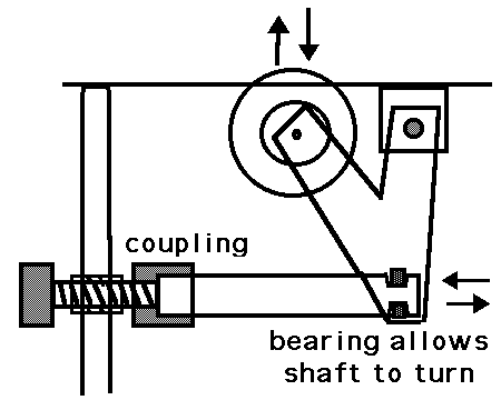
Now, I want to make some kind of mechanism, to lift the motor with blade up and down in some limits, so cutting depth is adjustable within limits. I want it to be easy like turning a knob on the front side of a frame (I hope you can imagine).
What I am asking you, is help me with an idea, of how this could be easily and efficiently achieved. Could it be done with screw jack and in what way? I am not a mechanical engineer, so I don't have much experience with mechanics, also I don't usually get good ideas about mechanic solutions. So I am turning on you guys, to help me with my project. I will be thankful for any advice and ideas.


