
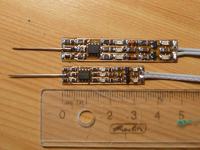
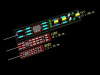
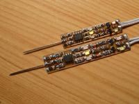
The device was designed in 3 versions:
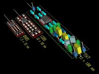
- 0805 – size 7.5x35mm
- 1206 – size 10x50mm
- THT – size 15x100mm
THT version was designed specially for members of digital electronics course (conducted by “Koło Naukowe SENSOR”).



When the probe is connected to less than 1.67V, red diode lights, green diode doesn't light before 3.33v. When it's connected to voltage between 1.67-3.33V, yellow diode lights. The pin detector contains two additional diodes – green and red one. When signal goes to hi/low, diode green/red lights for a moment, gradually turning off for 0.3s. Detector diodes slightly light every time – sometimes, when pins are very short, diodes don't catch it and don't light on, but that can be detected just looking on the brightness of control diodes – they will be slightly brighter. The detector gets impulses of about 20us long.
The circuit:
Whole device is powered with 5V set up on P1 and P2. End of the test probe is connected to P3. Resistors R1 and R2 create a voltage divider, which sustains 2.5V on the pin – to prevent from chaotic changes of state when device isn't connected to anything. R1 and R2 are 1Mohm, therefore even a weak signal can change 2.5V on another value – to test it, just touch P1, P2 or P3 with finger.

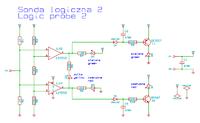
LM358 contains two operational amplifiers, which in this device work as comparators. Comparing voltage of probe with the master voltage (1.67, 3.33V) from R3, R4, R5 divider. Someone can say that TTL standard is 0.8 and 2.0V but CMOS is mostly used now. After some tests, this kind of divider was designed: 3 above resistors (R3-5) of 220k of resistance (why 220k? read further).
In unknown state, comparator U1A has on output 0, and U1B has 1. This makes the current to flow from B to A – switching on yellow diode. In the high state, both comparators give 0, and on low state they give 1.

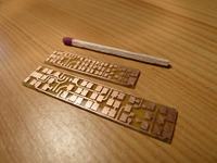

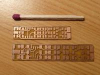
Idea to create possibly the smallest device forces to use most popular solutions. The pin detector is a simple peak detector and a simple RC with transistor. Firstly, the low state detector will be explained (red diode): on high state, voltage is on the output of U1A which, besides lighting the diode, charges C3 capacitor. D6 diode blocks the current to not “go back”. The C3 capacitor with R10 resistor create an easy time circuit which discharges through base-emmiter of T2 transistor. In this time, T2 is open and the current flows through D7 diode which gradually dims it as the C3 capacitor discharges. In unknown state, the detector diode should slightly light – to get this effect 220kohm resistor was used and a sufficient capacitor to get a good dying out time (this are the R3-5 resistors).
The high state detector works the same, just in the opposite direction. Normally U1B gives high state when it has low state or unknown on input. When the input voltage exceeds 3.33V, the comparator closes its output to ground, what causes lighting the green diode and immediate discharge of C2 capacitor through D4 diode. PNP transistor opens and lights D5 diode as long as the capacitor isn't empty. In the time as C2 charges, through R9 and base-emmiter of transistor, the diode gradually dims.

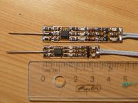

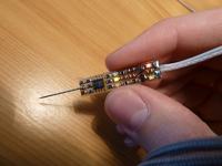

Now the effect of slightly lighting of detector diodes will be explained . It's because of a small frailty in LM358 – its voltage on output can change from 0 to 3.8V and no more (on 5V). Therefore, a small current flows through base of T1 PNP transistor through R9, D4 to the output of U1B. This effect isn't so bad as it was explained earlier (it allows to detect very short pins by watching brightness of diodes).
Assembly:
All small elements are in 1206 or 0805 housings, LM358 is in SO9, and transistors in SOT23. No holes are needed – smd welding isn't so hard!


All files from KiCAD, and PDF can be found on the original thread.
More free project can be found on the site:
Leon Instruments
Link to original thread (useful attachments) –
Miniaturowa sonda logiczna z wykrywaczem szpilek