Continue to Site

Welcome to EDAboard.com

Welcome to our site! EDAboard.com is an international Electronics Discussion Forum focused on EDA software, circuits, schematics, books, theory, papers, asic, pld, 8051, DSP, Network, RF, Analog Design, PCB, Service Manuals... and a whole lot more! To participate you need to register. Registration is free. Click here to register now.

Microphone noise problem related to PSU

lunatic_ash

Newbie
Newbie level 3
Joined
Aug 18, 2024
Messages
4
Helped
0
Reputation
0
Reaction score
0
Trophy points
1
Activity points
27
Hi guys.

I bought a brand new Telefunken U47 microphone in April 2024
I had used it with no problem, but a few days ago, a slight but noticeable hum noise occurred around 120Hz.

you can see the EQ image here in the picture

noise .PNG


I googled and found a similar case. Someone said it's an electrolytic caps problem in the power supply.
https://repforums.prosoundweb.com/index.php?topic=23670.0

I'm not gonna repair it by myself, but really want to know what the problem is.
I've already sent an email to Telefunken, but still waiting.

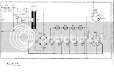
I took a picture of the inside of PSU, and you can see here

KakaoTalk_Photo_2024-08-18-16-48-21.jpeg


Can you guys tell me which parts function as filters? (someone told me to check the brown ones, but not sure about it cause I'm a totally layman)

I want to replace them with exactly the same model, and I think I need to order before visiting a repair shop.
 
Last edited by a moderator:
Probably the capacitors although there could be other reasons. They are the three brown cylinders on the left of the board. They all eventually fail but I'm surprised they died so soon on a relatively new unit. Normally you would expect 5+ years before hum becomes noticeable. They are not expensive to buy and easy to replace.

I'm not sure where you are but my guess is you have 60Hz mains power at your wall sockets. That is the clue, the bridge rectifiers (the four gray things with silver bands at one end near where the yellow and green wires reach) convert the 60Hz AC into pulsed DC at a rate of 120Hz. The capacitors act as reservoirs to hold the pulses at a steadier level before feeding the voltage regulator circuit. If the capacitors become inefficient the reservoir holds less and the pulses start to show across them and then conduct to the rest of the circuit.

Brian.
Thank you so much for your kind explanation. Your knowledge helps me a lot. Really appreciate it.
Yes, you are right. Like what you said, I'm using 60Hz, 220v power.

I just ordered the capacitors(brown ones)
Hope replacing those capacitors will solve the problem :)

Have a good weekend.
 
In your picture there's no sign of problems in the electrolytic capacitors (bulging, leaking, etc). I actually would suspect a bad solder joint. Looks like everything was soldered by hand, and there are many pads without any solder visible. I would first touch up each joint with fresh solder to see if that fixes the issue.

Also if you're on 220VAC, I assume you set the selector switch to 230V, not 115V?
Yeah I select 230, not 115 :)

I disassembled the PSU again and took a picture of the back side of the board.

I think it looks terrible. Even tho I have literally no knowledge about it, I can feel it.. lol

Plz look into it.

IMG_3296.jpeg


Is it bad??

How could the PSU of 10000 dollars microphone be soldered like this?
 
Last edited by a moderator:
Looks like the kind of PCB I would have designed by hand 50 years ago, but gold plated (or is the solder mask that color?) for show.
I would estimate in production that would cost maybe $25 US + cost of the box. My guess is that's an LM317 adjustable regulator on the heat sink. Even the internal grounding doesn't seem well thought out for ripple elimination.

Brian.
 
I remember seeing a network analyzer designed by a U of M student that was put into milled aluminum block and gold plated so it would be easy to solder coax braid. Now that definitely looked like a $100k box. It is somewhere in the bottom of Hudson's Bay with the rest of the R&D Black Brandt rocket back in the late '70's.
 
I disassembled the PSU again and took a picture of the back side of the board.

I think it looks terrible. Even tho I have literally no knowledge about it, I can feel it.. lol
Actually looks a lot better from the bottom, at least every pad has solder on it. Hard to tell if they're actually good joints though.
How could the PSU of 10000 dollars microphone be soldered like this?
Unfortunately high-end audio is an extremely predatory market. That power supply cost maybe 100$ at most to make. I'm guessing the mic was not much more.

The mic might actually work as well as the original u47. But $10K is still a ripoff.

Looks like the kind of PCB I would have designed by hand 50 years ago, but gold plated (or is the solder mask that color?) for show.
Looks like the substrate is black, and there is no soldermask at all.
 
Actually looks a lot better from the bottom, at least every pad has solder on it. Hard to tell if they're actually good joints though.

Unfortunately high-end audio is an extremely predatory market. That power supply cost maybe 100$ at most to make. I'm guessing the mic was not much more.

The mic might actually work as well as the original u47. But $10K is still a ripoff.


Looks like the substrate is black, and there is no soldermask at all.
Substrate is dark green. Everything is so far apart soldermask is unnecessary.
 
Hi,

instead of relying on smoothing capacitors only .. I´d rather use some voltage regulation / stabilisation.

But it depends on how you want to treat your device: for better quality or to keep the original circuit.

Kaus
 
Giant picture, hard to download, hard to see, wasting resources, even compressed...RESIZED
Hi,

instead of relying on smoothing capacitors only .. I´d rather use some voltage regulation / stabilisation.

But it depends on how you want to treat your device: for better quality or to keep the original circuit.

Kaus

Do you mean this kinda thing?

I searched on google

IMG_3302_1.png


Is it easy to install?

I’m not gonna do it by myself, but studying is quite interesting.
 
Last edited by a moderator:
Hi,

Do you mean this kinda thing?
Yes, this is one (popular) of many.

Is it easy to install?
Anyone, who uses it should read it´s datasheet.
Generally yes: basically add two capacitors and you are done. What kind of capacitors and what value should be given in the datasheet.

I don´t know how much current is drawn from the supply. Thus it´s hard to give detailed assistence.
But if done correctly it should be easy to reduce the 120Hz hum by a factor of 100.

I’m not gonna do it by myself, but studying is quite interesting.
If you do an internet search about "voltage regulators" or "voltage regualtor circuit" .. i strongly recomend to keep on reliable informations from
* semiconductor manufacturers (datasheets, application notrs, design notes, online design tools)
* universities
* reputable designers

... mainly because there is so much crappy information around.
What you can expect form a good information:
* description of working principle
* specifications in numbers and units, and tolerance
* design recommendations
* example schematics (complete, with part values)
* part value calculation
* additional - more detailed informations ...

Bad descriptions
* have short, incomplete informations
* don´t tell what to care about
* miss to give part value (calculation)
* often show wrong schematics
* often give wrong informations

Klaus
 
I had used it with no problem, but a few days ago, a slight but noticeable hum noise occurred around 120Hz
Check if you are now connected to another socket differing from the one in the previous days, Many years ago I had a problem with an ECG equipment that exhibited noise artifacts only afternoon (perhaps due to some machinnery on the same building energy bus), and I solved it by adding a metal plate right below the PCB board, grounded to earth. Since your case is already metalic, you could check if there is a connection between the chassis and the ground pin on the power socket (with the appropriate safety care).
 
Out of curiosity I looked for schematics for the PSU. Apparently been iterated and cloned many times, all are basically are just an isolation transformer + bridge rectifier followed by a few stages of RC filters, like below. Nominal output voltage around +105VDC (since the microphone was tube-based):
1724073088216.jpeg


Seems like someone did add slightly more modern circuitry on this board, but it's unclear what function it has. There's no way it's directly regulating the 105V output by itself...

A word of caution to the OP if you plan on tinkering with this: The PSU and microphone both involve hazardous voltages. I recommend against powering up any of the circuitry while it's in this disassembled state.
 

Attachments

  • 1724073054156.jpeg
    1724073054156.jpeg
    42.9 KB · Views: 19
There is already a TO-220 and heat sink on the board, and a multi-turn trimpot so I guess it is already regulated. The transformer has two 115V secondaries so it is obviously a high voltage supply and that puzzles me if it is only a few months old.

What kind of microphone is it, maybe electrostatic?

Brian.
 
It's capacitive mic with high impedance input tube preamp.. ..about the b+ regulation; eg. lm317 floating can regulate the anode supply. Tube needs that much voltage to stay away starved plate condition and stay more linear. Tube always adds a bit of harmonics for ear pleasing sound.. I wouldn't judge the caps..solder joints neither though i'd have no reason NOT to repair at least cap minuses to be looking way more flown.. I'd take a deep look in to grounding and xlr pin 1 type of problems..at least before suspecting the caps.. is it sure that the tube heater is dc? In the old ages they often were not, and a fault in tube was able to create hum..if it's dc, is it clean..? :)
 
Interesting point about the tube heater. At first I thought the device on the heat sink might be a regulated DC for the heater but if you look closely there are only two wires leaving the PCB, marked "GND" and "B+". The twisted white/blue wires with suspicious solder joints only link the sockets together, they don't connect to the PCB. So if this is a new product, where does the heater supply come from and why is it using tubes in the first place.

I note the schematic in post #16 has no heater supply either unless it uses a second supply linked through the sockets. The 105V itself certainly wouldn't supply heaters, especially if 40mA was its limit.

Brian.
 

LaTeX Commands Quick-Menu:

Similar threads

Part and Inventory Search

Welcome to EDABoard.com

Sponsor

Back
Top