electronicsman
Full Member level 5

I have few clarifications on the MCLV-2 board software and the schematics. I have attached the source code of AN2520 application noted, schematics of the board and AN1292 application note.
Q1. Referring to the userparams.h file
Does 4.4Amps represents the capability of the hardware to measure the phase currents or the maximum current the board can generate using FOC algorithm? I am not sure if i am making any sense. But suppose i reduce the 1.65V to 1V does it mean the board can measure and generate 6.1 Amps as per the formula above?
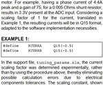
Q2. In the attachment from the AN1292 I don't understood the importance of the scaling factor? Can some one guide me to understand it? Why should i multiply with Q15(-0.5)

I am reading 2 to 3 Microchip application notes and source code together.
Q1. Referring to the userparams.h file
Code:
// Following parameters for MCLV-2 board
// Gain of opamp = 15
// shunt resistor = 0.025 ohms
// DC offset = 1.65V
// max current = x
// (x * 0.025 * 15) + 1.65V = 3.3V
// x = 4.4Amps
Does 4.4Amps represents the capability of the hardware to measure the phase currents or the maximum current the board can generate using FOC algorithm? I am not sure if i am making any sense. But suppose i reduce the 1.65V to 1V does it mean the board can measure and generate 6.1 Amps as per the formula above?
Q2. In the attachment from the AN1292 I don't understood the importance of the scaling factor? Can some one guide me to understand it? Why should i multiply with Q15(-0.5)

I am reading 2 to 3 Microchip application notes and source code together.