Vermes
Advanced Member level 4


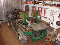
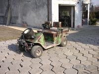
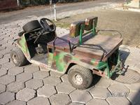
The purpose of the melex transformation was to start it up with low costs. This vehicle is necessary to pull a small trailer.
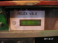
Two main difficulties which can occur while making the transformation are: to get the accumulators (new ones are too expensive) and make the PWM driver of sufficient capacity. Additionally, a LCD display, that shows the parameters of the ride, work of the engine and the PWM driver, can be made.
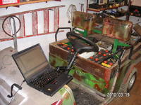
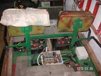
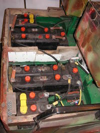
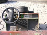
Accumulators can be taken from a dead electric cart. They do not have too much capacity, but for the melex it is enough. The dimensions of accumulators (especially their height) are the reason why it is impossible to mount the original seat. That is why the seat is made of waterproof plywood.
Originally welded accumulators need to be cleaved, then linked by copper bars. The bars can be made of copper tube fi 18mm.
20 cells connected in series gives 40V.
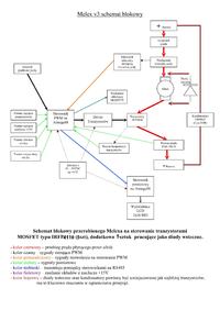
The PWM driver is a simplified version in comparison with a two-way one. In order to change the ride direction, an original current driving switch with microcontacts is used. The microcontacts send the signal to the PWM driver. Then the current flow to the engine is stopped when the direction is being switched.
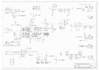
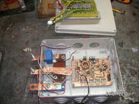
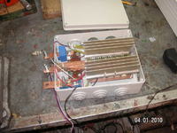
The PWM controller is made of two plates placed one above another. The bottom plate is a system with Atmega88 microcontroller. AC, communication module RS485 and measuring circuits are also present there. The top plate is feedback LEDs and capacitors transistors module.
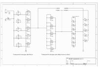
5 parallel linked transistors IRFP4110 and 5 transistors as LEDs were used, and also 7 capacitors 1000uF/63V.
As power, LM2576HV system was used. The current measurement on LEM HAS-200s.
The driver makes the measurement of accumulators voltage, engine current, 15V AC voltage, rpms, the temperatures of engine and transistors.
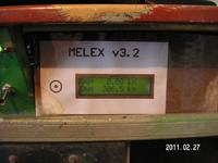
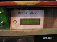
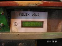
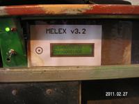
Data is sent to visualization system by RS485. That means a need to use another driver with Atmega88. It can convert and show the data on a 2x16 BIG display.
The frequency of PWM is 8kHz. The work of engine is silently heard, but it can be an advantage because it's easier to know if the driver works. When fully actuated (about 90% time of ride), it is quite silent.
At 16 kHz, the transistors were getting hot.
Below, there are some diagrams and pictures.
Link to original thread – Melex
Last edited: