uWave
Newbie

Hello everyone,
My colleagues and I are having some debate on the most accurate and correct way to measure passband ripple. We have read literature on the topic and researched it but there is always different opinions and interpretations on this topic. I was interested in getting some input from other professionals hoping to finally put this to bed. Any help, info or direction is greatly encouraged and certainly appreciated on this end.
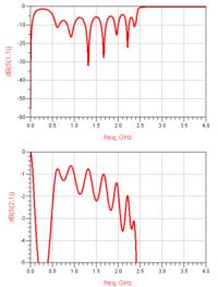
FWIW we design mostly passive chebyshev type filters. There appears to be a big differential in theoretical/design ripple and actual ripple recorded on the test bench once the part is fabricated. There also seems to be some confusion between a "ripple" specification and "passband flatness" or "amplitude variation" specifications. It is my understanding that flatness and ripple are different measurements altogether and that it is possible for one to be compliant and not the other. The biggest question is how one would measure ripple on a network analyzer in real time. Is there a way to measure ripple or is it calculated? I understand ripple to be the same as mismatch loss calculating it from a filters return loss. Basically the better the return loss, the less ripple within the band. It has been suggested that any peak to adjacent peak within the passband is measured as ripple.
I apologize if this topic has been posted previously. I searched and still could not find the answer I was looking for. Anyone who can chime in on this topic is greatly appreciated. Illustrations may be useful also. Thank you!


