chiques
Full Member level 3
- Joined
- Nov 21, 2007
- Messages
- 170
- Helped
- 2
- Reputation
- 4
- Reaction score
- 2
- Trophy points
- 1,298
- Location
- California
- Activity points
- 2,556
How can I measure the inductivity of an antenna operating at 2.45 GHz using a VNA?
Follow along with the video below to see how to install our site as a web app on your home screen.
Note: This feature may not be available in some browsers.
A resonance happens only when a capacitance and inductance are connected in series or in parallel.
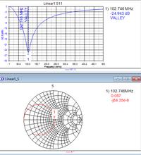
Your case looks like a series resonance at 102 MHz. You must find both parts, L and C. Smith chart center indicates no resonance a perfect impedance match (to 50 Ohms).
Sorry about that. I was fiddling around with the tuning. Here is my 2.45 circuit. The fact that my S11 has such a low return loss and my smith chart is fairly well centered at 50 Ohms still does not qualify my circuit as "resonant" at 2.45 GHz?:shock:
Is this a case where 1/(2*pi*f*C)=2*pi*f*L ?
So 'C' and 'L' can be arbitrary? Basically you can lower one and increase the other???
Is it so? Impedance is converging to short circuit (s11 = -1) for high and low frequencies, so it rather looks like parallel resonance, I think.Your case looks like a series resonance at 102 MHz.
Out of curiosity: Why would it make a difference between a series or parallel resonant circuit?
So 'C' and 'L' can be arbitrary? Basically you can lower one and increase the other???