Continue to Site

Welcome to EDAboard.com

Welcome to our site! EDAboard.com is an international Electronics Discussion Forum focused on EDA software, circuits, schematics, books, theory, papers, asic, pld, 8051, DSP, Network, RF, Analog Design, PCB, Service Manuals... and a whole lot more! To participate you need to register. Registration is free. Click here to register now.

meassuring resistance of heating element (soldering iron)

Status
Not open for further replies.

someperson

Newbie level 4
Newbie level 4
Joined
Oct 24, 2011
Messages
5
Helped
0
Reputation
0
Reaction score
0
Trophy points
1,281
Activity points
1,339
Hi guys,

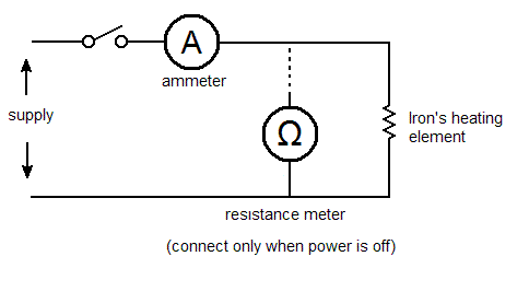
I bougth a hakko 907 clone, and I'm trying to meassure resistance of it's heater element.

For this I have a (not center tapped, single output) transformer giving me 24V @ 3A.

The goal is (to learn) and to keep a temperature as constant as possible in order to take readings of it's sensor's resistance, such that I can make a profile out of them; yes, my goal really is to make a soldering station.

While I can use AC or DC for the heating element, my best guess is that it would be eassier to use DC and a mosfet as switch, I might be wrong, but in either case, it would be nice if I could meassure resistance of the heating element no matter if it's on or off. That would allow finer control over it's temperature.

I guess a voltage divider should hang off the final switching device, perhaps with an opamp acting as a voltage follower or something.

While I've done small things with microcontrollers (atmegas mostly), I'm not an expert on electronics, and much less when it comes to analog.

So it would be really appreciated if somebody could give me a kick off, some starting point or hints.

Regards!
 

Hi kak111,

Thanks, though not really helpful concerning my original question.

Will continue invesigating.

Thanks for all your links,

Regards,
 

This circuit eliminates the need for a special sensor because it senses the temperature
of a soldering iron heating element directly from its resistance.
and controls DC power with MOSFet switch
**broken link removed**
 

At least one of the linked circuitsTemperature-Controlled Soldering Iron Circuit Diagram does exactly what you are asking for. (Don't know, if it actually works with your your solder iron's heater element). May be, you didn't notice the circuit. Or not understood it.
 

At least one of the linked circuitsTemperature-Controlled Soldering Iron Circuit Diagram does exactly what you are asking for. (Don't know, if it actually works with your your solder iron's heater element). May be, you didn't notice the circuit. Or not understood it.

Thanks both guys, and sorry!

Yes, this wouldn't work with my specific iron as is, but that would be a matter of using an amplifier rated for 24V input or a bit more (hakko is 24V/50W).

And no, I don't fully understand it yet, but I'm already catching up on amplifiers.

What's the purpose of L1, though? As per the transformer, it seems to me it's only purpose is to provide isolation.

Regards,
 

Measure the current through the heater element when it's on. Measure its resistance when it's off.

Connect a bulb or a l.e.d. across the element just to remind yourself not to try to measure resistance when it's on.

Repeat as necessary.
 

Use a hot plate or portable electric stove element to heat the tip and adjust the temp. Thermal couple would be best temp sensor. The more metal mass to clamp to tip the easier it will be to keep constant temp for sensor measurement.
 

Thanks guys,

@RCinFLA, I think the opposite. I might be wrong, but having more thermal mass on the tip means slower thermal propagation, so it would be more difficult to accurately know temperature at it's end, overall if the soldering iron in continuous use (where continuous means soldering a component, hanging the iron while you get another to solder it, and so on).

Also, thermocouples seems a bit more difficult to handle than the sensor this soldering iron comes with, due to the need for cold-junction compensation. I also plan to buy one of those when I have this one working.

@Syncopator. The current/resistance measure was a great idea. Thanks, I'm working on it.

I've read about shunt resistor circuits for current measurement these last days, as is the method I'd be using for the current part, and so I wanted to ask whether it really makes a difference if the soldering iron is driven with AC or DC?

So far, everything I wanted to do seems a bit more complicated with AC, but I've also read the use of DC helps developing magnetization over time.

I guess this wouldn't relate to this specific soldering iron, as heating and sensing elements are embedded on a ceramic cylinder.

But if there's some other reasons for using one over the other when it comes to soldering irons, would be glad to know.

Regards,
 

@Syncopator. The current/resistance measure was a great idea. Thanks, I'm working on it.

I've read about shunt resistor circuits for current measurement these last days, as is the method I'd be using for the current part, and so I wanted to ask whether it really makes a difference if the soldering iron is driven with AC or DC?

A couple of multimeters, one on a suitable current range, the other on a suitable ohms range, connected like this will do.


irontest.gif


It doesn't matter as far as the iron is concerned whether you apply a.c. or d.c., it depends on if you have a meter which can measure a.c. current or not.

Switch the supply on for a while, note the current. Switch off and measure the resistance. Disconnect the resistance meter and repeat at suitable intervals.
 

Also, thermocouples seems a bit more difficult to handle than the sensor this soldering iron comes with, due to the need for cold-junction compensation. I also plan to buy one of those when I have this one working.
Do you mean, the Hakko 907 iron has a separately connected temperature sensor? Then you don't need to measure the heater resistance to know the temperature.
 

A resistance meter usually works by applying a known DC voltage and measuring current. (As with our typical VOM, DMM.)

Measuring current draw of an AC appliance can be done by inserting a known resistance inline, and measuring voltage across the known resistance.

Here's a working schematic. It should be possible to substitute an electronic circuit for the meter. Notice it does not need a reminder to detach it.

27_1320022584.gif
 

Hi guys,

@Syncopator, thanks. I would do that for getting max. values, but my point is doing it through a circuit.

@FvM, yes. It has it's own sensor, whose profile is the one I'm trying to get.

@BradtheRad, thanks!

This is more or less what I have so far (see attachement).

As per how to pass a little voltage across the resistor when the mosfet is off, I don't know. It would be nice if advantage could be taken on the 5 volts supply for this, so the resistor wouldn't turn on while the mosfet is off and I'd be meassuring resistance.

Else, I'd probably try to heat the resistor a bit by turning the mosfet fuly on for a while, and then give just a small pulses from time to time, wide enough to get it's resistance, such that I know when I should turn the mosfet on again.

What you think?

Regards,
 

Attachments

  • board.pdf
    14.1 KB · Views: 124

Your schematic clarifies what you've set out to do.

I posted with the assumption your soldering iron took its supply from household current, and that that was the reason you had to disconnect it while you take resistance measurements.

You've devised a method which looks like you can get it to work, in concept.

It will depend on being able to adjust the components which affect the op amp's response, so that it (a) receives stable readings across the current sense resistor, and (b) yields stable output.

Question:

Your op amp gets a 5V supply. Yet its inputs are in contact with the 24v supply through resistors. Is your resistor network (which may include the heating element, I can't be sure) intended to divide down that higher voltage, in order not to expose the op amp to 24V?
 

I assume, that the original heater controller will rather use triac control of an AC voltage and thus achieve a better utilization of the transformer.

After you clarified that the iron is equipped with a temperature sensor, I don't see any purpose of a heater resistance or current measurement.
 

Status
Not open for further replies.

Similar threads

Part and Inventory Search

Welcome to EDABoard.com

Sponsor

Back
Top