Continue to Site

Welcome to EDAboard.com

Welcome to our site! EDAboard.com is an international Electronics Discussion Forum focused on EDA software, circuits, schematics, books, theory, papers, asic, pld, 8051, DSP, Network, RF, Analog Design, PCB, Service Manuals... and a whole lot more! To participate you need to register. Registration is free. Click here to register now.

MAX232/MAX3232 heating up.

Status
Not open for further replies.
Cost is not an issue for me! I only need to build one circuit that is doing the job correctly for a long time.

From what I see in official schematics....

Pin 10 and 11 are internally connected to 5V through a 400K resistor!

Pin 13 and 8 are internally connected to the ground through a 5K resistor.
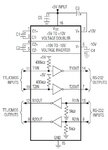
MAX232.jpg

For pin 10 and 11 it means, by adding the 4.7K ohm resistor, you are actually decreasing the total resistance to something around 416Kohm!!! Isn't it an unnecessary thing to do if the pin resistance is that much by itself?

And now something that will blow your minds. When I check the pin resistance to the Vcc, I see 12 Mega Ohm!! On a brand new IC that I have ordered from an official seller! I don't know if this could be the source of the problem!

Dear Klaus, Do you also agree with Andre? That it is better to put R3 and R4 on the RS232 side? Just want to have some ideas.... I am a little obsessed with this circuit. My main area of expertise is Optimization Algorithms (Heuristic mainly!) and I always want to optimize everything I find, even in daily life!

- - - Updated - - -

And about the ESD Considerations:

Is the R and C in parallel in between the Chassis and Ground enough? like this? Or am I doing it wrong?
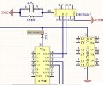
esd.jpg
 
Last edited:

Hi,

Datasheet of MAX3232:
The transmitter inputs do not have pullup resistors.
Connect unused inputs to GND or VCC.

What RS232 IC exactely do you use?

I'd say the resistors are an improvement.

Klaus

- - - Updated - - -

Added:
For pin 10 and 11 it means, by adding the 4.7K ohm resistor, you are actually decreasing the total resistance to something around 416Kohm!!! Isn't it an unnecessary thing to do if the pin resistance is that much by itself?
4.7k || 400k = 4.64k. Not 416k

Your circuit: if you put a 22R to the RS232 IC VCC, then I'd add a 1u X7R to GND.

Klaus
 

Hi,

Datasheet of MAX3232:


What RS232 IC exactely do you use?

I'd say the resistors are an improvement.

Klaus

- - - Updated - - -

Added:

4.7k || 400k = 4.64k. Not 416k

Your circuit: if you put a 22R to the RS232 IC VCC, then I'd add a 1u X7R to GND.

Klaus

Thanks Klaus

Currently I am using MAX232CPE... I don't have MAX3232 around.

Which resistors are improvement? There are too many resistors on the circuit :laugh:

Of course I know how to calculate parallel resistors :laugh: The exact solution is: 4645.416357 and I don't know why I copy pasted that!!! :thumbsdown:

Yes I have bypassed the MAX232 ... but I erased it from the schematic when I copy pasted it to the mspaint... you can see some changes on the left side of the circuit!

What about my question about the ESD!? Could you please read my last post carefully once more?!
 

Hi,

With Max232 the internal resistor at Pins10 & 11 is 400k.
With Max3232 there are no internal resistors.

12M: measure the current to GND, when the IC is powered up. Then calculate R.

Isn't it an unnecessary thing to do if the pin resistance is that much by itself?
You lower it by a factor of about 85.

Resistors: R3, R4.....
Not move. I'd add two 100R resistors at the RS232 side. I see an improvement.

ESD RC is fine.

Klaus
 

Long and short of it:

Get the datasheet for your chip and wire it up as per the given example.
If you have a problem it's either:
1. Bad construction - don't use breadboard for these - I recommend vero or similar
Keep components close and pins trimmed.
2. Check components - are they from reputable sources (at one time there were many dodgy components floating around)
(ask me about UART chips from china sometime)
3. Use the datasheet from the manufacturer of the chip you have - not a generic one.
4. Check your power supplies carefully - put a scope on or change it for an alternate if you don't have a scope
5. Connect your RS232 cable to a different device or just loop it back

If it still does the same - pray to whichever demon it is that's teasing you to leave you alone !
 

well, I had this problem recently. In my circuit I used only one set of Tx-Rx but T1in/out & R1in/out was open. MAX become heated while power is on. I tried many ways, and I soldered T1in & R1in to GND. Now MAX is not heated and working well. I don't know what was the logic behind that but its working.
 

Status
Not open for further replies.

Similar threads

Part and Inventory Search

Welcome to EDABoard.com

Sponsor

Back
Top