yefj
Advanced Member level 5

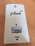
Hello i am trying to interface a board with J-ling EDU Segger debugger shown in the attached photo.
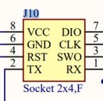
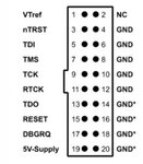
The board has 8pin connection but the jlink device has 20 pin connection.
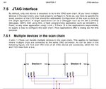
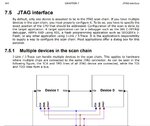
I have tried to look in the manual bellow to find out what each output pin one that device represents
i have attached a photo of the schematics of the board connection.
how do i connect between the board and the JLINK EDU device?
Thanks.
