M.R.O.
Newbie level 1

Hello,
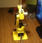
I would like to present my hobby and also thesis project. It's a manipulator with a the charming name 608.
Main aims of project were:
- Building a manipulator with 6 degrees of freedom,
- Minimum dimensions with ensuring functionality and similarities same as in robots working in industry
- Maintain wider understanding of aesthetic.
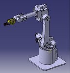
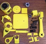
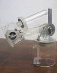
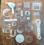
First of all I did some research into how to control DC engines (I've planned to use them (price)). Next step was to create CAD model of manipulator. As CAD software I choose Catia V5. Construction materials that I took into consideration were PMMA, steel, aluminium. They are relatively easy in treatment and generally available. A quite important criterion was to ensure appropriate stiffness to the whole construction and the fact that I didn't have access to milling machine or 3D printer. So according to that it has to be designed in such a way that I'll be able to create all parts on my own. Robot has bearings in axes 1 – 4. Finally from steel I've made shafts of axes 1-2 and 2-3. The arm holder, rotating platform and few smaller parts were made from aluminium. PMMA is the most used material, mainly I use plate 2 mm and 4 mm. Parts were cut on water jet machine afterwards I gave them the desired shape by heating it with hot air and bending on the edge of a desk. I can write a lot about the creation process, but better way is to answer the questions.
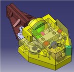
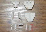
Gripper was created later because it wasn’t necessary for the operation of the manipulator and I have to cut costs. CAD model was also created in Catia and I decided to print it because of the very small size. It was quite problematic to find the engine, gearbox and bearings that will fit. In side gripper there are also two limit switches and it's controlled through force.
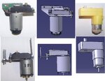
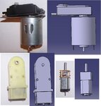
DC motors with gearboxes are responsible for movement. Motors from axes 1-3 came from old printers and gearboxes form RC servos. As a position feedback I've used optic encoders. Final position resolution is >=0,1 degree. Engines are controlled by PID regulators.
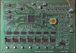
Manipulator is controlled by ATxmega 128A1. At the beginning circuit came on universal PCB. Finally PCB was designed in AD13. Maybe I won't write a lot about electronic, schematic is attached. Robot is supplied by 12V DC. In side driver two impulse transformers are hidden which provide voltage (3,3V and 5V). Code for uC is written in eclipse environment, C language. Writing software was the most time consuming part. As standard on uC is running DMA, ADC, PWM, WDT, USART, PLL, timers.
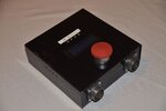
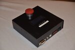
Whole driver is closed in metal housing. On the top there is an emergency button, LCD display, 4 switches and 3 LED. In the front panel we can find a DB15 connector. It's used for flashing uC and connecting some external devices (some pins from uC and all voltages are provided though it). Next we have the voltage connector, usb connector, fuse and main power switch. On the other side of the housing we have sockets to connect the manipulator. Inside the robot there are 38 wires in which 34 are used, 4 of them are provided as excess. The fan is placed in the bottom of housing.
At the moment we have 3 methods to control the robot.
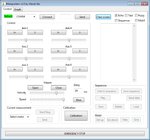
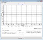
- Via PC (RS-232), I've developed an application written in Lazarus (Delphi). Using it we have full control of the manipulator i.e. measuring current of motors, measuring excitations, creating movement sequences, modifying PID gains, calibration.
- Via Android device. I've created a simple application in App Inventor. It allow us to control each axes of the manipulator, calibration, running sequences and sending single orders.


- Via buttons placed on driver housing. It also allows us to control each axis and that is important if we want to control the robot in the way mentioned above we need to enable that manually on driver.
Well, it’s hard to say that the project is “done”. To a large extent I was able to get close to an industrial manipulator, and thus I am able to test variant algorithms, control systems, kinematics etc. The difference is that mine doesn’t cost as much as industry ones.
If we're talking about cost:
- Electronic parts 200 Euro
- Mechanics parts 400 Euro
As I wrote in the introduction, the project was successful that it was the base of my thesis. The topic was" Fuzzy logic based controller for a 6R manipulator" and it's a topic for another article. Anyway in comparison to normal PID regulator sum of overshoots were decreased by 64,5% which was a surprise even for me.
To sum up, the project was quite important and successful. Mainly because I learned a lot from the different fields of knowledge and this is most important. As it used to be in those kind of project there are still things which can be done better or upgraded. More or less I achieved my goal and I was able to get close to an industrial manipulator with a functionality and similarities in operating.
I AM NOT THE AUTHOR OF THE RIDING PLATFORM
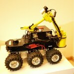
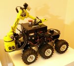
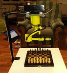
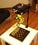
Some video showing how it works, more of them on YouTube channel (I recommend Vodka Car ). Have a nice watch.
Best regards.
I would like to present my hobby and also thesis project. It's a manipulator with a the charming name 608.
Main aims of project were:
- Building a manipulator with 6 degrees of freedom,
- Minimum dimensions with ensuring functionality and similarities same as in robots working in industry
- Maintain wider understanding of aesthetic.
First of all I did some research into how to control DC engines (I've planned to use them (price)). Next step was to create CAD model of manipulator. As CAD software I choose Catia V5. Construction materials that I took into consideration were PMMA, steel, aluminium. They are relatively easy in treatment and generally available. A quite important criterion was to ensure appropriate stiffness to the whole construction and the fact that I didn't have access to milling machine or 3D printer. So according to that it has to be designed in such a way that I'll be able to create all parts on my own. Robot has bearings in axes 1 – 4. Finally from steel I've made shafts of axes 1-2 and 2-3. The arm holder, rotating platform and few smaller parts were made from aluminium. PMMA is the most used material, mainly I use plate 2 mm and 4 mm. Parts were cut on water jet machine afterwards I gave them the desired shape by heating it with hot air and bending on the edge of a desk. I can write a lot about the creation process, but better way is to answer the questions.


Gripper was created later because it wasn’t necessary for the operation of the manipulator and I have to cut costs. CAD model was also created in Catia and I decided to print it because of the very small size. It was quite problematic to find the engine, gearbox and bearings that will fit. In side gripper there are also two limit switches and it's controlled through force.


DC motors with gearboxes are responsible for movement. Motors from axes 1-3 came from old printers and gearboxes form RC servos. As a position feedback I've used optic encoders. Final position resolution is >=0,1 degree. Engines are controlled by PID regulators.


Manipulator is controlled by ATxmega 128A1. At the beginning circuit came on universal PCB. Finally PCB was designed in AD13. Maybe I won't write a lot about electronic, schematic is attached. Robot is supplied by 12V DC. In side driver two impulse transformers are hidden which provide voltage (3,3V and 5V). Code for uC is written in eclipse environment, C language. Writing software was the most time consuming part. As standard on uC is running DMA, ADC, PWM, WDT, USART, PLL, timers.
Whole driver is closed in metal housing. On the top there is an emergency button, LCD display, 4 switches and 3 LED. In the front panel we can find a DB15 connector. It's used for flashing uC and connecting some external devices (some pins from uC and all voltages are provided though it). Next we have the voltage connector, usb connector, fuse and main power switch. On the other side of the housing we have sockets to connect the manipulator. Inside the robot there are 38 wires in which 34 are used, 4 of them are provided as excess. The fan is placed in the bottom of housing.


At the moment we have 3 methods to control the robot.
- Via PC (RS-232), I've developed an application written in Lazarus (Delphi). Using it we have full control of the manipulator i.e. measuring current of motors, measuring excitations, creating movement sequences, modifying PID gains, calibration.


- Via Android device. I've created a simple application in App Inventor. It allow us to control each axes of the manipulator, calibration, running sequences and sending single orders.


- Via buttons placed on driver housing. It also allows us to control each axis and that is important if we want to control the robot in the way mentioned above we need to enable that manually on driver.
Well, it’s hard to say that the project is “done”. To a large extent I was able to get close to an industrial manipulator, and thus I am able to test variant algorithms, control systems, kinematics etc. The difference is that mine doesn’t cost as much as industry ones.
If we're talking about cost:
- Electronic parts 200 Euro
- Mechanics parts 400 Euro
As I wrote in the introduction, the project was successful that it was the base of my thesis. The topic was" Fuzzy logic based controller for a 6R manipulator" and it's a topic for another article. Anyway in comparison to normal PID regulator sum of overshoots were decreased by 64,5% which was a surprise even for me.
To sum up, the project was quite important and successful. Mainly because I learned a lot from the different fields of knowledge and this is most important. As it used to be in those kind of project there are still things which can be done better or upgraded. More or less I achieved my goal and I was able to get close to an industrial manipulator with a functionality and similarities in operating.
I AM NOT THE AUTHOR OF THE RIDING PLATFORM


Some video showing how it works, more of them on YouTube channel (I recommend Vodka Car
Best regards.