mcmsat13
Member level 5

Hi everyone!
This code is written in CCS C Compiler. The hardware device is 12F675.
I used AN0 and AN1 as the analog voltage sensor inputs.
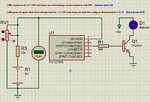
When the value at AN0 is 1.00V (Normal acceptable voltage level), GP2 becomes High and the transistor drives the LED on. Once High, it should remain High unless the voltage at AN0 is decreased to 0.90V (LVD), and GP2 becomes Low. Once in this state, it will remain Low until the voltage level is >= 1.00 then it becomes High again (LVD Auto Recovery)
HVD part works the same way.
If the voltage at AN1 reads 1.20V (HVD) , GP4 becomes high and Q2 turns the Q1 off. Once HVD is detected at 1.20V, the condition remains until the voltage at AN1 is decreased to 1.10V (HVD Recovery set point), the GP4 becomes Low, the Q2 turns off and D1 is again on.
See the circuit and source code below:
Moderator action: link removed
Now, my problem is this: as the above circuit utilizes two analog pins, AN0 and AN1 and then two digital pins GP2 and GP4, I wanted to use only AN0 as input and only GP4 as the output to perform the same functions but everything I do does not work. I am very new to the MCU code writing, hence I think other people can help me. I am just learning with practice.
Please can someone here help me modify this one below to offer the same functions as the one in the link I posted above?
The LED comes on at 1.00V and should remain on unless the voltage is increased to 1.20V (HVD) then it will off.
When off at 1.20V which is HVD, it will stay off until the voltage is decreased to 1.10V (HVD auto recovery)
The led will also off at 0.90V (LVD) and stays off unless the voltage level comes up to 1.00V (LVD auto recovery)
I wonder if these two functions could be incorporated into one pin like this?
Moderator action: link removed
Any help is appreciated.
I can also accept C codes written MikroC Pro
Thanks all.
Last edited by a moderator:


