[SOLVED] LTC3780 Current limit
- Thread starter luckym
- Start date
- Status
- Not open for further replies.
mtwieg
Advanced Member level 6

It already implements a current limit in the controller. If you want to make it a current regulator (as opposed to a voltage regulator with a current limit) then it might be possible, but will require modifications to the control loop, and output voltage limiting protection.
luckym
Member level 1

Thanks for reply, The current control in the IC is part of inner control loop (if i understand that...) and don't know how to utilize this for current limit. I want to keep the voltage regulator and add current limit. I want to use it for charging Pb-ACCU, so need voltage regulator with current limit.
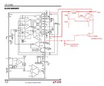
I've tried this wiring (look at the figure) but unsuccessful - it oscillates. I had only LM358, may be wrong OA... Is this right way? or should I try something different (schematic)?
thanks for help..


I've tried this wiring (look at the figure) but unsuccessful - it oscillates. I had only LM358, may be wrong OA... Is this right way? or should I try something different (schematic)?
thanks for help..

Last edited:
D.A.(Tony)Stewart
Advanced Member level 7

- Joined
- Sep 26, 2007
- Messages
- 10,298
- Helped
- 1,868
- Reputation
- 3,741
- Reaction score
- 2,518
- Trophy points
- 1,413
- Location
- Richmond Hill, ON, Canada
- Activity points
- 64,908
Thanks for reply, The current control in the IC is part of inner control loop (if i understand that...) and don't know how to utilize this for current limit. I want to keep the voltage regulator and add current limit. I want to use it for charging Pb-ACCU, so need voltage regulator with current limit.
I've tried this wiring (look at the figure) but unsuccessful - it oscillates. I had only LM358, may be wrong OA... Is this right way? or should I try something different (schematic)?
thanks for help..
View attachment 112027
Vref comparator has far too much gain and no BW limits. Do you know control theory?
What you want is
1. slow response rise to CC limit,
2. then CV limit,
3. then when I= 5% of CC limit , foldback to CV float for Pb batteries and latch.
This topology does not do that. Search site for solutions.
mtwieg
Advanced Member level 6
Yes, but the inner current mode control loop has an upper limit past which it won't allow peak inductor current to increase no matter what (see page 22 of the datasheet). But it's only a peak inductor limit so it does not accurately regulate the actual output current over a wide input voltage range. Also it seems to have built in foldback limiting, which may be a problem for implementing external current limiting.Thanks for reply, The current control in the IC is part of inner control loop (if i understand that...) and don't know how to utilize this for current limit.
The schematic looks reasonable, but it's not surprising that it oscillates. Injecting current into the Ith node (actually, pulling current out of Ith) may provide better results than injecting into Vfb. Are you actually working with the real circuit, or are you simulating in LTspice?I want to keep the voltage regulator and add current limit. I want to use it for charging Pb-ACCU, so need voltage regulator with current limit.
I've tried this wiring (look at the figure) but unsuccessful - it oscillates. I had only LM358, may be wrong OA... Is this right way? or should I try something different (schematic)?
thanks for help..
View attachment 112027
luckym
Member level 1
Vref comparator has far too much gain and no BW limits. Do you know control theory?
No... I know very little about this. and this is me problem...
- - - Updated - - -
Also it seems to have built in foldback limiting, which may be a problem for implementing external current limiting.
ok, maybe this explains the strange behavior when I connected this circuit to VFB pin.
[/QUOTE]The schematic looks reasonable, but it's not surprising that it oscillates. Injecting current into the Ith node (actually, pulling current out of Ith) may provide better results than injecting into Vfb. Are you actually working with the real circuit, or are you simulating in LTspice?
I'm working on real circuit....
Now I'm thinking about this: I don't need fast response in current limiting... There is a potentiometer - top resistor in voltage divider. If I replace it with digital potentiometer will be the stability of the control loop influenced? I can sense current with MCU and set voltage via this pot.
It would work like an outer slow control loop. At the start I'll begin with voltage setting low, and gradually increasing until current limit. Is this a way?
- Joined
- Jan 22, 2008
- Messages
- 53,713
- Helped
- 14,812
- Reputation
- 29,921
- Reaction score
- 14,446
- Trophy points
- 1,393
- Location
- Bochum, Germany
- Activity points
- 303,667
Your circuit oscillates because the current control path has effectively infinite gain by using an OP in comparator configuration. You can turn the circuit into a PI controller by adding a RC circuit. As you said, the current control loop must not be fast, so there shouldn't be a problem to find a stable configuration.

luckym
Member level 1
- Status
- Not open for further replies.
Similar threads
-
-
-
Limit line differences between EN55015 EN55022 and EN55032?
- Started by cupoftea
- Replies: 1
-
-
SCR Crowbar - latching current and gating current question
- Started by Magnethicc
- Replies: 8
