Dr Phibes
Newbie level 3

Help Needed - LT1513 SLA Battery Charger Simulation with LTSpice
Hi,
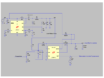
This is probably a basic question, but I'm struggling to understand why (in LTSpice at least) a resistor appears to be needed upstream of the battery's positive terminal in a LT1513 circuit.
None is shown in the LT1513 datasheet, but it is included in the LT1513 test fixture, and this circuit (which is may attempt at a DC UPS with a SLA battery) appears to need it.
Image:

Any ideas? Feel free to comment on the rest of the circuit - surprisingly few references to doing this with these chips on the web.
Thanks in advance,
Lee
Hi,
This is probably a basic question, but I'm struggling to understand why (in LTSpice at least) a resistor appears to be needed upstream of the battery's positive terminal in a LT1513 circuit.
None is shown in the LT1513 datasheet, but it is included in the LT1513 test fixture, and this circuit (which is may attempt at a DC UPS with a SLA battery) appears to need it.
Image:

Any ideas? Feel free to comment on the rest of the circuit - surprisingly few references to doing this with these chips on the web.
Thanks in advance,
Lee
Last edited:
