Vermes
Advanced Member level 4


This device is a logic analyzer (registrar). It will help solve the problems with all kinds of communication devices, I2C, SPI, RS232, 1WIRE or own protocol.
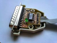
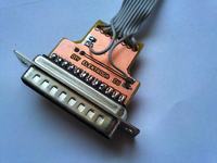
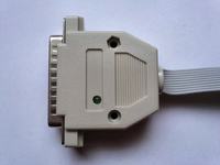
The whole analyzer is an input circuit of LPT port, samples are received and saved in real time. It is possible to get to one million samples per second from 8 channels simultaneously. 74xx245 buffer protects the LPT port from possible surges. The buffer power is taken from the STROBE line of the port, unfortunately, this line has a very little current available (from about 250uA to about 2mA). The use of a buffer in HC version would reduce the power consumption to a minimum and allow powering from STROBE pin – just make sure that the buffer gets at least 3V (for HC, for LS or HCT versions it is 4,7V) for all lines in the state L. If this condition is not met, the whole has to be powered from an external source. When choosing a buffer, you should also pay attention to whether it accepts signals above its own power supply.
Remember that the system is not galvanically isolated from the computer. If you do not keep precautions, you may damage the LPT port or the motherboard. Galvanic isolation can be performed using optocouplers, but they have to be fast and they need to be powered. The cable should not be too long, IDC 10-wire tape with a length of about one meter was applied. Using longer cables is not recommended, because the parasitic capacity and rebounds between its wires effectively obstruct the measurements at higher speeds. To avoid rebounds between the wires, a wider tape may be used and there should be a wire connected to the mass between each wire with a signal.
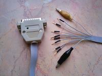
The ends of cables arbitrary, grapple Tests can be used because of their low price. The analyzer would be used in prototype systems using the contact plate, so wires signal were ended with pinheads. They can be numbered, but the most important is to remember that the first channels is near the cable of the mass and the second one is near the power cable. Wires of the mass and power were ended with alligators.
On the internet you can find a lot of applications that support such a LPT port analyzer – for example very good and extremely easy to use – The Fabulous Logic Analyzer:
TFLA-01 -- The Fabulous Logic Analzyer #1


Sample video of transmission of two bytes by using I2C (course 4 and 5 are next video, pasted for comparison). In this case, you can see the lack of response of the system by the flag of ACK confirmation – a fault was quickly located and eliminated.

Link to original thread (attachment) – Analizator stanów logicznych na LPT