Continue to Site

Welcome to EDAboard.com

Welcome to our site! EDAboard.com is an international Electronics Discussion Forum focused on EDA software, circuits, schematics, books, theory, papers, asic, pld, 8051, DSP, Network, RF, Analog Design, PCB, Service Manuals... and a whole lot more! To participate you need to register. Registration is free. Click here to register now.

logarithmic amplifier for HF

neazoi

Advanced Member level 6
Joined
Jan 5, 2008
Messages
4,155
Helped
13
Reputation
26
Reaction score
15
Trophy points
1,318
Location
Greece
Activity points
37,164
Hi,
I have seen many logarithmic DETECTORS, but I would like to find a logarithmic pre-AMPLIFIER that could operate from about 1MHz to 30MHz region.

I would like to use it for experimenting with different RF blocks.
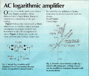
I have seen this circuit which seems simple, but this is only for audio and I do not know if a fast opamp (which one?) will achieve the same result on HF.

My preference is on discrete circuits if possible (but not limited to them).

Could you help?
Thanks
 

Attachments

  • ac_logarithmic_amplifier.jpg
    ac_logarithmic_amplifier.jpg
    113.7 KB · Views: 167
Search in Analog Devices, I'm sure you'll find something. You can also realize this amplifier by using bipolar transistors but it might be less efficient and accurate.
 
Last edited:
The most common use of log amps for RF is to generate the RSSI signal and control gain.
Even more important radar IF amplifiers+detectors.

In any case they are dedicated nonlinear signal processing blocks, useless e.g. for receiving AM signals.
 
Discrete ccts suffer from discrete matching many stages and parasitic C.


The app. is not mentioned yet, but this should work for radar too.
  • Usable to 250 MHz
  • 44 dB dynamic range
  • ±2.0 dB log conformance
  • 37.5 mV/dB voltage output


Discussion of tails.

Logarithmic Amplifier Performance
–75 dBm to +5 dBm Dynamic Range
≤1.5 nV/√Hz Input Noise
Usable to >50 MHz
 
Last edited:
To resemble a logarithmic curve this response from an NPN could have potential (with further adjustment). It's operated just near the threshold of turn-On.
The rightmost scope trace is X-Y (input-versus-measured).

NPN at margin of operation depicts logarithmic response.png
 

    neazoi

    Points: 2
    Helpful Answer Positive Rating
To resemble a logarithmic curve this response from an NPN could have potential (with further adjustment). It's operated just near the threshold of turn-On.
The rightmost scope trace is X-Y (input-versus-measured).

View attachment 191452
Thanks so much thats very interesting!
Just a question, Isn't it an exponential curve instead of log?
 
The term log amp used interchangeably for both log detectors and true log amplifiers and sometimes even for detector log video amplifiers (DLVAs). Each is a very different functionally.
If you want to build a true RF log amplifier search for the now very old and long obsolete Plessey SL531 data sheet, it has a basic schematic of the device. It does work up to at least 70MHz if you build one using reasonable (5GHz ft) RF transistors. I had to do it once to replace the function in a radar receiver.
You will find that if you use it in a HF receiver that because of the non linear function that intermodulation distortion will be a major problem.
 

    neazoi

    Points: 2
    Helpful Answer Positive Rating
The term log amp used interchangeably for both log detectors and true log amplifiers and sometimes even for detector log video amplifiers (DLVAs). Each is a very different functionally.
If you want to build a true RF log amplifier search for the now very old and long obsolete Plessey SL531 data sheet, it has a basic schematic of the device. It does work up to at least 70MHz if you build one using reasonable (5GHz ft) RF transistors. I had to do it once to replace the function in a radar receiver.
You will find that if you use it in a HF receiver that because of the non linear function that intermodulation distortion will be a major problem.
Thank you so much!
Indeed, the circuits on the net confuse log detectors, log video amplifiers and log amplifiers, I can confirm that.
That excellent chip you mentioned can go as high as 50Euros but is an great resource and they give the internal schematic.
I have already performed experiments in applying exponential (anti-log) amplifiers on HF and yes, they intermodulate easily and yes they require a peak filter on their input to help on that, else they are useless. As long as you keep the bandwidth and the gain low, they do work though.

The only pitfall in this chip is the huge price. The circuit at post #1 is a great promise in that extent, if it can be implemented on HF. Fast 100MHz opamps cost as low as 5Euros nowadays and it can be set for all 3 modes, linear, log, exp.
I searched for more info on the circuit but It is only mentioned in a tiny space on a page of an old HAM radio magazine.
The text mentions a FET, but the picture shows an opamp.

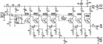
Also, I would like to show you, around the midle of this page https://lea.hamradio.si/~s53mv/spectana/sa.html he mentions this logarithmic detector which can be implemented using discrete transistors. I am not sure if this is a logarithmic amplifier or detector, can you please let me know?
 

Attachments

  • sa09.gif
    sa09.gif
    29.1 KB · Views: 90
Last edited:
Isn't it an exponential curve instead of log?
We can get one or the other by measuring at different comonents, and as referenced to ground or supply. Here's a simpler example using a single diode. Two lissajous figures are plotted. One seems to graph the root, the other seems to graph the power. Yet their mathematical relationship is the counterpart of the other.

Similar performance can be measured from a circuit built around transistor behavior.

diode curves V vs A lisssajous (both orientations).png
 
Hi,
I have seen many logarithmic DETECTORS, but I would like to find a logarithmic pre-AMPLIFIER that could operate from about 1MHz to 30MHz region.

I would like to use it for experimenting with different RF blocks.
I have seen this circuit which seems simple, but this is only for audio and I do not know if a fast opamp (which one?) will achieve the same result on HF.

My preference is on discrete circuits if possible (but not limited to them).

Could you help?
Thanks
I simulated the circuit you posted but did not like the results. It looks like a dual-slope audio pot which approximates a log scale by changing the gain sensitivity.

He reports the log ratio is 3:1 for Ri:Rf using a 50k pot. The only thing that looks log scale is 200:1 on the pot.
with a 60k pot the ratio is 40k:20k. With 50k it is Ri=36k, Rf=12k as shown on his plot.

So I would say this is not a good log amp but in the audio industry might be called an S curve compressor.

https://tinyurl.com/259b85wz my sim

1718127162138.png
 

    neazoi

    Points: 2
    Helpful Answer Positive Rating
Would this fit?
I am looking for up to 30MHz operation.
The intersting thing is that it operates at as low as 0.001v (although more than 0.01v recommended)
As far as I can see is a true log amplifier and not a detector?
This is not very expensive either.
 

Attachments

  • tl441.pdf
    702 KB · Views: 103
It is a log amplifier not detector right? Because I see the output to be taken through a series diode.
I wonder if this 5k T resistor is a thermistor?
Is a log amplifier. Yes, 5kT is a thermistor.
 

    neazoi

    Points: 2
    Helpful Answer Positive Rating
Also bypass the electrolytics with ceramic capacitors, it is designed for audio and at 30MHz the electrolytics will present considerable impedance.

Brian.
 

    neazoi

    Points: 2
    Helpful Answer Positive Rating
discrete is def not the way to go. semiconductor chip ones, with carefully balanced gains rule the world.

how about a log detector, where you have a detector diode and shape its output to be logarithmic. and you can add a 2nd detector diode with a fixed gain amp in front of it, to extend range. THAT you might conceivably get to work in discrete form.

remember, you need to worry about device drift over temperature, power supply variations, gain aging....
 
Why do you want this design? Application description speaks volumes while your question is very misleading with false assumptions. Please define your Purpose.

The image of the design is not a “log amp” but it is a bipolar dual slope compressor.


Searching for “Log Amp” designs will also fool search engines and AI bots because this is too vague and includes limiters, detectors and wastes time.

The math expression of log is invalid for zero and RF certainly crosses zero.

Perhaps “bipolar log RF amp”.

A "true" log amp cannot go through zero, which is required for bipolar input signals, but there are degenerate forms of log amps which go smoothly through zero but in that region the response is only "quasi-logarithmic.

Now you need to define the error limits for offset, low level gain errors. For both the “log section” and "quasi-logarithmic” zero crossings the units are in mV/dB].


Bipolar Dual slope is not “log” unless you have large error tolerances .

The ratio on the pot determines the ratio of the slope relative to the Vf of peak pot current expected. The input peak waveform must exceed 2 diode drops for the 2nd slope to be present and wiper offset determines the polarity and ratio of the dual slopes .

Also Falstad’s user donation built-in of a Log Amp” is actually a “bipolar anti-log amp” simulation using the quadratic current response. When used with negative feedback then the inverse or the “anti-anti”’s cancel out. 😎

Many are still curious why an RF log amp? LiDAR, RADAR, RFID, micro power harvester? Or something else?
 
Last edited:

LaTeX Commands Quick-Menu:

Similar threads

Part and Inventory Search

Welcome to EDABoard.com

Sponsor

Back
Top