Continue to Site

Welcome to EDAboard.com

Welcome to our site! EDAboard.com is an international Electronics Discussion Forum focused on EDA software, circuits, schematics, books, theory, papers, asic, pld, 8051, DSP, Network, RF, Analog Design, PCB, Service Manuals... and a whole lot more! To participate you need to register. Registration is free. Click here to register now.

Load Current Limitation in LTC7000 High Side MOSFET Driver.

Status
Not open for further replies.

H2M

Member level 1
Member level 1
Joined
Aug 11, 2016
Messages
36
Helped
0
Reputation
0
Reaction score
0
Trophy points
1,286
Activity points
1,624
Hi
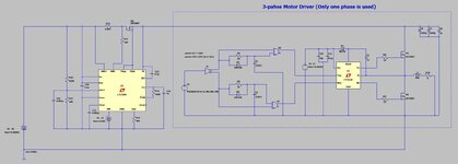
I'm trying to design a 3-phase motor driver. I want to have over current protection in my design, so I have used LTC7000 in order to have over current protection in my bus line. the problem is I can't raise the MOSFET current (Load Current) above 10 Amps! with any shunt resister LTC7000 will turn off the MOSFET when current reach above 10 Amps. Can anybody help me? I attached below my LTspice simulation.
 

Attachments

  • Capture.JPG
    Capture.JPG
    107.1 KB · Views: 336

MOSFET current will not go above your 50V in / 6 ohm load unless
you explicitly apply a short.

I guess you'd need to look at the DC-DC core to see if it, itself, is
meddling (like internal current sense for current mode control,
could house a "backstop" current limit?).

But you could just put a switch on the OCP FET drain and see what
happens with a simpler, more focused testbench of just the current
limit.
 

Hi,

What exact type of shunt did you use. Did you use Kelvin wiring technique?
Also, please show us your PCB layout.

Btw: BAT54 is specified for 30V only. You should use a higher voltage one.

Klaus
 

You are seeing this behaviour in simulation or real circuit?
I haven't made real circuit yet. I think I will only see this behaviour in simulation, I read datasheet carefully and I didn't see any tips about that. I don't understand how LTC7000 detect that the current is raised above 10 Amps! because the only thing that LTC7000 see is the shunt resistor voltage. There isn't any feedback to LTC7000 to detect load current except shunt resistor voltage.
--- Updated ---

Hi,

What exact type of shunt did you use. Did you use Kelvin wiring technique?
Also, please show us your PCB layout.

Btw: BAT54 is specified for 30V only. You should use a higher voltage one.

Klaus
Thanks for your point about BAT54, We used this shunt in previous prototype:


But our circuit didn't work as fast as possible and we have to change the design and use LTC7000. In previous prototype we used Kelvin connection as you can see below:
--- Updated ---

MOSFET current will not go above your 50V in / 6 ohm load unless
you explicitly apply a short.

I guess you'd need to look at the DC-DC core to see if it, itself, is
meddling (like internal current sense for current mode control,
could house a "backstop" current limit?).

But you could just put a switch on the OCP FET drain and see what
happens with a simpler, more focused testbench of just the current
limit.
Excellent attention, I tune current load using R10 and duty cycle, in this picture load current is set about 9 Amps. We need to detect load current up to 200 Amps.
--- Updated ---

Kelvin Connection
 

Attachments

  • Capture.JPG
    Capture.JPG
    52.7 KB · Views: 124
Last edited:

Hi,

does this hold for a slow rising curren t, or only for fast slopes?

In your SPICE schematic I do not see an RC input filtering, so I would asume there might be an impedance mismatch causing a high voltage drop across your shunt due to the shunt impedance for fast transients. Consequently, this leads to a limiting of your current. Have a look here [1].

[1] https://www.planetanalog.com/current-shunt-resistor-inductance-it-matters/

BR
 

Hi,

The shown PCB layout does not fit to the shown schematic.
Don't confuse us with random informations.
Please show the according PCB layout.

Klaus
 

I think you would be better using a LEM current sensor for your 200 Amps.
Kelvin connection for a 200Amp will be challenging.
So too the effect of layout and stray inductance etc.
Possibly also use IGBT, as FET will sweat trying to break 200Amps.
 

Hi,

The shown PCB layout does not fit to the shown schematic.
Don't confuse us with random informations.
Please show the according PCB layout.

Hi,

The shown PCB layout does not fit to the shown schematic.
Don't confuse us with random informations.
Please show the according PCB layout.

Klaus
Hi Klaus, The PCB layout that I have attached is for my previous version, I made that with a shunt resistor and current sensing circuit using Op-Amp. It wasn't as fast as possible and we should change our design and use LTC7000. Before making PCB I want to simulate it.
--- Updated ---

I think you would be better using a LEM current sensor for your 200 Amps.
Kelvin connection for a 200Amp will be challenging.
So too the effect of layout and stray inductance etc.
Possibly also use IGBT, as FET will sweat trying to break 200Amps.
LEM current sensors are extremely expensive for high current measurements. Also they are too big and we don't have enough space. We used shunt resistor and Kelvin connection in my designs and measured current up to 200 Amps without any problem. For more safety I need to add over current protection in my designs and now I have this issue with LTC7000 that it doesn't work when load current goes above 10 Amps.
There is a sample circuit in LTC7000 datasheet that mention 10 Amps contentious max. I decrease the value of shunt resistor and Also Iset resistor and I expect to reach currents more than 10 Amps, but it doesn't work.
--- Updated ---

Hi,

does this hold for a slow rising curren t, or only for fast slopes?

In your SPICE schematic I do not see an RC input filtering, so I would asume there might be an impedance mismatch causing a high voltage drop across your shunt due to the shunt impedance for fast transients. Consequently, this leads to a limiting of your current. Have a look here [1].

[1] https://www.planetanalog.com/current-shunt-resistor-inductance-it-matters/

BR
Hi, Thanks for your excellent point. I replaced my half-bridge with a simple resistive load and the problem solved. As you mentioned high ringing across shunt resistor due to parasitic inductance and high di/dt I should your a RC filter in my feedback path. I attached the simple circuit that it works properly with resistive load.
 

Attachments

  • Capture.JPG
    Capture.JPG
    68.3 KB · Views: 117
  • Capture.JPG
    Capture.JPG
    64.7 KB · Views: 122
Last edited:

Your Rsen is 50uR.....the noise will likely obliterate the measurement.
I dont even think its possible to properly kelvin connect that.
What about one of those Hall sensors from (i forget the name now), might by MPS, or ....i think its a Japanese company, forget the name.
 

Hi,

The PCB layout that I have attached is for my previous version
Let´s say you have two children. One is sick, the other is healthy.
Which one do you show to the doctor?

I won´t annoy you by asking for the same a third time.

Klaus
 

Hi,

Your Rsen is 50uR.....the noise will likely obliterate the measurement.
I dont even think its possible to properly kelvin connect that.

... that's possible and I have used 50u shunts. BUT, without impedance matching and a proper layout (shunt footprint) as well as good/on-point alloy connection you will not achieve your desired behaviour.

BR
 

Hi,


Let´s say you have two children. One is sick, the other is healthy.
Which one do you show to the doctor?

I won´t annoy you by asking for the same a third time.

Klaus
Hi Klaus,
I haven't made the new version with LTC7000 yet. I only attached that picture to show that I used Kelvin connection in my designs. As stenzer mentioned due to voltage ringing across my shunt resistor the LTC7000 went into OCP for higher currents. I replaced switching load with a simple resistive load and the problem solved. So I should put a RC filter in my feedback path. if I get results I will share it here. Also I found a good video related to LTC7000 that can be useful for others:

--- Updated ---

Your Rsen is 50uR.....the noise will likely obliterate the measurement.
I dont even think its possible to properly kelvin connect that.
What about one of those Hall sensors from (i forget the name now), might by MPS, or ....i think its a Japanese company, forget the name.
The problem with Hall sensors are low response time. I need a very fast OCP circuit.
 

Last edited:

I haven't made the new version with LTC7000 yet.
Are you talking about a real circuit? Then it´s urgent to show us your wiring!

Indeed if you don´t use a proper PCB (layout) then your test makes no sense at all. Read and follow the "Applications information", especially the "PC Board Layout Considerations" If you don´t follow them, don´t be surprised if the Circuit does not work as expected.

Or are you talking about a simulation?

Klaus
I am only talking about simulation. After that I will make real circuit with LTC7000. It's a very good IC and have all of protections that we need. In previous version I made OCP, OVP and UVP using multiple Op-Amps and compactors. It wasn't as fast as possible.
 

Hi,

--> Then show us your simualtion! .. not only a schematic.

You talk about "fast" .. then the much bigger problem is your 6600uF at the output.
This way it´s impossible to react "fast" on your MOSFET current.
-->If not MOSFET current, then tell us on which current it should react fast.

Math of the datasheet circuit with 10 A (top of page#24):
150k x 10uA = 1.5V
1.5V / 20 = 75mV
75mV / 5mOhms = 15A.
= 10A operating current + 50% headroom = 15A trip current..

So they guarantee a 10A operation. Even with some noise and ripple.
It will trip at nominally 15A.

A usual fuse operates the same way: If it has a holding current of 10A it maybe will trip at 15A.

Klaus
 

The problem with Hall sensors are low response time. I need a very fast OCP circuit.

No. -Some- Hall sensors are slow because they include a high gain low
bandwidth op amp to get a nice large scale linear signal. The Hall element
itself is fast and very low amplitude (per field stength / sensed current).
If your threshold of interest is high then your fastest OCP will be a
comparator and a low-Z fast sense element, bare. But with low signal
comes high noise sensitivity and you might need to add gingerbread
like leading edge blanking and soft start to make it all play nice.

You could look at bare Hall sensors, see what (mV/gauss?) can be had and
what kind of form factor (maybe a fat ferrite to enclose the wire doesn't
fit your frame?). If you can get more mV from a no-touch, no excess R
Hall setup than a hot, adds-R sense resistor then go for it. At least as far
as a bake-off (setting a plan in concrete based on Internet advice???).
 

Precision Measurements :


Thermoelectric, Kelvin, Noise :


PCB Considerations :


Regards, Dana.
Thanks for great resources
 

Have you considered a CT, as another way to get lossless
sensing? Many off-the-shelf options or you could roll your
own from many available howtos / tutorials and calibrate
it yourself.
 

Status
Not open for further replies.

Similar threads

Part and Inventory Search

Welcome to EDABoard.com

Sponsor

Back
Top