Continue to Site

Welcome to EDAboard.com

Welcome to our site! EDAboard.com is an international Electronics Discussion Forum focused on EDA software, circuits, schematics, books, theory, papers, asic, pld, 8051, DSP, Network, RF, Analog Design, PCB, Service Manuals... and a whole lot more! To participate you need to register. Registration is free. Click here to register now.

[SOLVED] LM3914 - What might "dot/bar logic" be?

Status
Not open for further replies.

d123

Advanced Member level 5
Joined
Jun 7, 2015
Messages
2,505
Helped
494
Reputation
992
Reaction score
525
Trophy points
1,393
Location
Spain
Activity points
27,148
Hi,

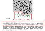
The LM3914 can light all LEDs/activate all outputs on a rising input similar to a VUmeter kind of thing or function more like a set of window comparators and only light one LED/activate one output at a time, e.g. 1V to 2V input is only output 1 on, 2V to 3V input is output 2 on but 1 off, 3V to 4V input is output 3 on but 1 and 2 off, and so on.

Tried to think about it, did a few simulations with the basic schematic shown below and added transistors to consecutively cut off the previous output to emulate dot mode with no success but can't imagine how this is done. Maybe parallel comparators referenced to the next reference voltage up or something? An enable/high Z pin on the comparators in the simplified schematic? Bar mode is easy to simulate, it's the same circuit as the simplified schematic.

Can anyone guess - or better yet, do they know - what the little box that says dot/bar logic may actually contain so as to perform the dot function, please?

Thanks.
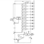
LM3914 block diagram.JPGlm3914 dot or bar mode selection.JPG
 

When Pin 9 is connected to the V+ Supply Voltage, you will get a Bar Display.
 
  • Like
Reactions: d123

    d123

    Points: 2
    Helpful Answer Positive Rating
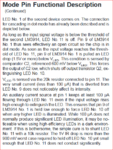
LM3914 Dot/Bar logic was explained in old National Semiconductor datasheets. For some reason TI has butchered them, deleting essential knowledge.
The logic actually has three functions: dot/bar/blanking.
LM3914 dot bar logic.pngLM3914 dot bar logic2.png
 
Hi,

Thanks for the replies. Nice NatSemi detailed description, thanks. I understand that pin 9 controls one mode or the other depending on whether it is - basically - high or low.

What I meant was: What might be the actual internal circuitry of the IC described as "dot/bar logic" in that little "black" (white) box that makes the device function in dot mode and make each previous/lower value comparator switch off at the threshold of the next one. I just can't imagine what that internal circuitry could be and would love to know.
 

You would need to find the Circuit Equivalent, than trace out Pin 9 On it.
I equivalent circuits for many IC's but Not for the LM3914, 3915 or 3916 series.

And Google didn't show it either.
 

Hi,

For the "bar" function, just comparators may be used.

For the "dot" function the outputs are combined with logic AND gates.
- when the next higher value comparator is ON then all the lower value outputs are "OFF".
For positive logic one may use an AND gate with one inverted input. ... and OR gates to combine all the higher value outputs.

Klaus
 
  • Like
Reactions: d123

    d123

    Points: 2
    Helpful Answer Positive Rating
Re; Butchering of data sheets.

I get it that nowadays semiconductor companies do not want to invest the time and effort required to write a very detailed datasheet.

But the existing datasheets, which have already been written, where all the effort and expense is already been spent, why re-edit them with fewer information? I don't get it.

That is the reason one should keep old databooks.

I used to have a series of Motorola Semiconductor databooks. The brown cover ones. In one of my many house moves, I left them behind.
I bang my head against the wall now.
 

I kept All the Old data Books, starting from about 1970.
TI, National, Motorola, On Semi, Harris, RCA, Unitrode, Exar, Raytheon, Linear, and some others.
 

Re: LM3914 - What might "dot/bar logic" be?

Hi,

Re; Butchering of data sheets.

I get it that nowadays semiconductor companies do not want to invest the time and effort required to write a very detailed datasheet.

But the existing datasheets, which have already been written, where all the effort and expense is already been spent, why re-edit them with fewer information? I don't get it.

That is the reason one should keep old databooks.

I used to have a series of Motorola Semiconductor databooks. The brown cover ones. In one of my many house moves, I left them behind.
I bang my head against the wall now.

Besides possible concerns over IP theft, and the evident dumbing down of absolutely everything we use these days ("Why?" is a good question - Are we all becoming more stupid or incompetent or something...?), maybe it's because it feels like nowadays people can't be bothered reading them beyond the first schematic they see and seem to have little interest in fascinating details beyong making something or other intrusive and unnecessary to improve my life in ways it must be a struggle to dream up such "usefulness" (and make money, I assume) from some IoT thing they're working on with an Arduino/Pi/Beagle/etc.? Just kidding. Maybe just kidding, maybe...

The now humble 555 datasheet went from one with tips, multiple applications and explanations, even super and "witty" cartoons, to the one with several "typical applications" to the current datasheet version I've seen with only the monostable/astable schematics and formulas and - I kid you not - an "LED flasher" typical application... Hans must be turning in his grave with despair.

If you can bear pdf versions, sites like Archive.org are a good place to look. Just for you, if you haven't seen these pages:

Motorola Databooks
1971 Motorola TTL Integrated Circuits Data Book
1966 Motorola Semiconductor Handbook 2ed Aug66
1994 Motorola Semiconductor Master Selection Guide
SEMICONDUCTOR DATA BOOKS
Databooks

These two seem to be about giving away, swapping or purchasing original paper copies and/or CD-ROM versions:
Vintage Semiconductor, Transistor & Integrated Circuit Data Books
**broken link removed**

Queen were right, unfortunately: "I want it all, I want it now." So is Idiocracy: It's the age of "Electrolytes and stuff."

Have fun!

- - - Updated - - -

Hi Klaus,

Hi,

For the "bar" function, just comparators may be used.

For the "dot" function the outputs are combined with logic AND gates.
- when the next higher value comparator is ON then all the lower value outputs are "OFF".
For positive logic one may use an AND gate with one inverted input. ... and OR gates to combine all the higher value outputs.

Klaus

Thank you so much for figuring it out. It had been puzzling (and "annoying") me for a few days. I really appreciate your having solved the configuration. Many thanks.
 

Status
Not open for further replies.

Part and Inventory Search

Welcome to EDABoard.com

Sponsor

Back
Top