Continue to Site

Welcome to EDAboard.com

Welcome to our site! EDAboard.com is an international Electronics Discussion Forum focused on EDA software, circuits, schematics, books, theory, papers, asic, pld, 8051, DSP, Network, RF, Analog Design, PCB, Service Manuals... and a whole lot more! To participate you need to register. Registration is free. Click here to register now.

lm3524n -12V voltage collapsing problem

Status
Not open for further replies.

g7pvs

Newbie level 4
Newbie level 4
Joined
Oct 21, 2011
Messages
7
Helped
0
Reputation
0
Reaction score
0
Trophy points
1,281
Activity points
1,353
I'm trying to make a -12V supply as part of a radio club project I'm working on (antenna analyser). As we have loads of lm3524n chips available I'm trying to use one for producing the -12V.
I'm using the circuit from figure 11, page 12 of the national datasheet for the LM2524D/LM3524D. www.national.com/ds/LM/LM2524D.pdf

The components I'm using are:
Rf = 30k
Fosc = 10kHz
Rt=10k
Ct=10nF
L1=47mH ( 154 ohm internal resistance)
Co=47uF
R1=100R
R2=1k
Io should be up to 31mA
delta Vo = 0.03V
Q1 = BC327
D1 = 1N4148

The measured Vo is -12.04V with no load or a load of 10k ohms, however if I try to draw more current the output voltage collapses.

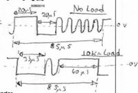
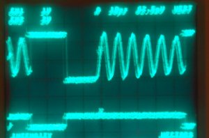
I've looked at the junction of Q1,D1 and L1 with an oscilloscope and I get approx 12V for 20uS, approx -12V for 20uS then sinewave for 45uS (approx 5 full waveforms), then repeated when no load is applied.

With 10k ohm load I get approx 12V for 40uS, approx -12V for 33uS then sinewave for 12uS (approx 1 full waveform), then repeated.

I've not worked with switch mode power supplies before, so am unsure as to what I've done wrong. Any help would be appreciated.

Best Regards

Trev
 

A hand calculation shows, that the series resistance of the inductor doesn't allow 30 mA output current. And ideal inverting boost converter with 50 % duty cycle has an average inductor current of 60 mA in CCM. This current level would cause most of the supply voltage dropping at the series R.
 

I know the inductor isn't ideal and the internal resistance will cause problems if I try to draw higher currents, but as far as I can see that doesn't explain the problem I'm having.

A load resistor of 8k2 causes the inductor to get hot and Vo to collapse to -4.1V, it continues to slowly collapse further, but I disconnected the supply as the inductor was getting rather hot.

A load of 8k2 should draw approx 1.5mA at 12V and as far as I can see at that current the voltage dropped across the inductor due to the current flow through it should only have a minor effect on the output voltage.

The inductor I am using is Farnell part number 107-7047 - I had some of them and thought as the circuit I'm using will probably only draw between 15 and 20mA I might be able to use it for the prototype, or at least prove that it will work OK in principle.

If the inductor is the problem, I would be grateful if you would be able to suggest something more suitable

Best Regards

Trev
 

Show us what the waveform on the cathode of D1/collector of Q1 looks like, before and after the voltage starts drooping. Sounds like it's going discontinuous but the large variation in duty cycle you describe implies something else is going on.

Also make sure the polarity of the output bypass capacitor is correct for negative output voltages.
 
Last edited:

Hi,

Below is the waveform - I'm not sure what is causing the sinewaves.


The sinewaves don't quite go as low as the lowest negative part of the waveform and for the one not under load the sinewave magnitude gradually decreases.

The capacitor is definitely the correct way around.

I do have some 10uH inductors, which are physically larger and so have much less internal resistance, would I be able to somehow use one of those, or would the switching frequency need to be higher than the lm3524n will work at?

Best Regards

Trev
 

Those sine waves are normal. It means your supply is operating in discontinuous mode.

I've found one definite issue in the datasheet though. The device is limited to about 45% duty cycle operation. That would easily explain why your voltage is drooping when you apply a heavier load. You're reaching that duty cycle limit.

That doesn't really explain the inductor heating though. That's still a mystery.
 

Hi,

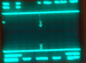
I've taken photos of the waveform when it is OK and when the output collapses.

3_1319216284.jpg
44_1319216284.jpg


Sorry about the quality of the images!

Best Regards

Trev
 

Hi,

I gather from the messages so far that the problem is related to the internal resistance of the inductor, therefore I've ordered some toko 8rb 22mH inductors which I believe have a resistance of 30 ohm and a maximum current of 80mA.

Are these suitable or should I have ordered something different?

If they are suitable, when they arrive will exchanging one of them for the 47mH inductor fix the problem?

Best Regards

Trev
 

I know the inductor isn't ideal and the internal resistance will cause problems if I try to draw higher currents, but as far as I can see that doesn't explain the problem I'm having.

You have been initially specifying up to 30 mA output current. Did you understand that this is impossible with your inductor?

Another question is, if the circuit possibly "locks" at lower output currents, e.g. with 8k2 load. The circuit doesn't implement inductor current limiting, so it possibly doesn't you the favour to stop the inductor current at the point, where you would like it. The current increase in one cycle is much higher than the inductor can handle. The control loop can switch to a mostly on state, but still don't transfer sufficient energy to the output.

The problem is, that you can't easily instruct the circuit to limit the duty cýcle respectively inductor current to a value, where the output voltage drops again. (You actually can by adding an external voltage limiter circuit to the control amplifier output).

I've found one definite issue in the datasheet though. The device is limited to about 45% duty cycle operation.
The shown circuit has both PP-driver outputs in parallel and thus goes up to 90% d.c.

Personally, I would choose a suitable inductor. 10 µH seems much too low for a low current, moderate switching frequency converter.

P.S.: The 22 mH 30 ohm type seems basically suitable. It may be nevertheless necessary to limit the 3524 duty cycle.

By the way, there are dedicated inverting boost converter ICs on the market, that can perform better. Even the cheap good old MC34063 is better in so far, that it implements an input current limiting.
 
Last edited:

If I were you I would go with a much smaller value inductor (like 1mH max), and increase the switching frequency (to at least 20KHz so it doesn't make audible noise). If you want the output ripple to be lower, then use an additional LC filter on the output.

I still can't see why your inductor is getting hot, there's really no way that should happen if the circuit is built properly, even with a lossy inductor. Still the first thing you should try is a better one.
The shown circuit has both PP-driver outputs in parallel and thus goes up to 90% d.c.
Yeah you're right, didn't realize the outputs were push pull.
 

Hi,

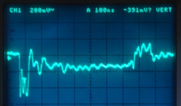
Thanks for all the help so far, I've changed a few components and am now getting the 31mA I wanted out of it at -12.04V, unfortunately there is quite a lot of ringing:

55_1319711183.jpg


The components I'm now using are:

Rf = 30k
Fosc = 417Khz
Rt = 2.4k
Ct = 1nF
L1 = 1mH (3.5 ohms)
Co = 47uF (36V)
R1 = 100R
R2 = 1k
Q1 = 2N4033
D1 = 1N4148

Any help would be appreciated.

Best Regards

Trev

---------- Post added at 11:37 ---------- Previous post was at 11:32 ----------

Hi Again,

Some of the ringing will I believe to be due to the fact that whilst swapping and changing components I've built the psu on prototyping board, I'll try to get it made properly with short leads as soon as I can.

Best Regards

Trev
 

Building the circuit on a PCB or copper clad board would definitely help. Also add some smaller, high frequency capacitors (like 1uF, ceramic or polypropylene) to the input and output. Self-resonance of the inductor may be an issue as well.
 

Hi,

Thanks for the reply,

I added a 1uF capacitor on the output, which more or less halved the ripple, unfortunately under load the 2N4033 also got toasted (became very hot and if left started smoking and then stopped working). I'm not sure why this would happen, but previously when I've drawn too much current from this circuit the voltage has collapsed and if left for more than a few seconds the transistor gets toasted.

As normally the transistor doesn't get hot I'm not sure why this is happening.

After previously toasting a BC327 I had changed the transistor from a BC327 to a 2N4033 because it has a higher current and power rating (Ic max for 2N4033 is 1A, and for BC327 is 800mA), do I need to use a transistor with a higher Ic for this circuit to work?

Best Regards

Trev
 

As previously mentioned, a basic problem of the suggested polarity inverter circuit is not to provide any input current limiting. You could try with a sense resistor in series with the inductor and the 3524 CL inputs.
 

I added a 1uF capacitor on the output, which more or less halved the ripple, unfortunately under load the 2N4033 also got toasted (became very hot and if left started smoking and then stopped working). I'm not sure why this would happen, but previously when I've drawn too much current from this circuit the voltage has collapsed and if left for more than a few seconds the transistor gets toasted.
There's got to be something wrong with the circuit then. The 2n4033 should be able to dissipate half a watt easily in ambient air, and you should not be drawing that much from the input. In fact you shouldn't even need to use an external transistor; the internal ones should be adequate.
 

In fact you shouldn't even need to use an external transistor; the internal ones should be adequate.
I don't think that the voltage range of the internal transistors allows inverting operation.
 

Status
Not open for further replies.

Similar threads

Part and Inventory Search

Welcome to EDABoard.com

Sponsor

Back
Top