kamalavignesh
Newbie level 6

- Joined
- Oct 4, 2010
- Messages
- 11
- Helped
- 0
- Reputation
- 0
- Reaction score
- 0
- Trophy points
- 1,281
- Location
- Vijayawada
- Activity points
- 1,368


In my opinion, it's O.K. at the negative rail, and thus LM324 is often used in simple single supply circuits. Of course the device has some limitations like class B output stage.The lm324 is a pretty terrible op amp, and has very poor input and output range, especially on a single supply.
In my opinion, it's O.K. at the negative rail, and thus LM324 is often used in simple single supply circuits. Of course the device has some limitations like class B output stage.
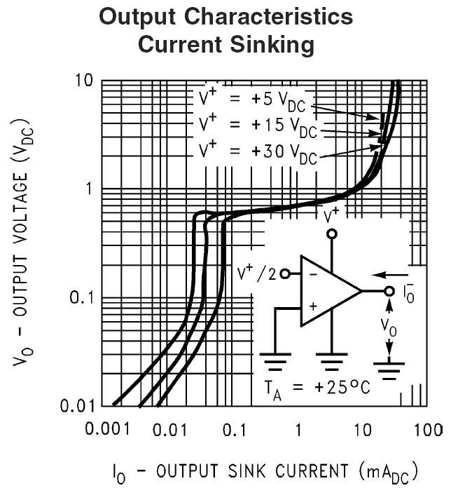
I can't remember a similar behaviour. According to the (National) datasheet, the output swings below 10 mv at zero output current. By placing a pulldown resistor, you get down to effectively zero output voltage, so a current sense amplifier referred to negative supply can work well.The output will never go below 0.5V unless its sourcing current.
Although rather old, it's still an acceptable solution for slow and medium speed applications, where inherent limitations like the class B cross-over distortions don't count. And it's really cheap.It still blows my mind whenever I open up the control board of large power supplies and see LM324s used all over the place.
The output stage has an internal 50uA current sink for pulling it down, but even that will probably only work to 0.2V. If you're sinking more current than that 50uA, then the output can never get below 0.5V. At least it shouldn't, given the output structure, and I've never seen it happen in real life. The national datasheet I've seen has the output range specified with pull down resistors.I can't remember a similar behaviour. According to the (National) datasheet, the output swings below 10 mv at zero output current.
The purpose of the 50 uA current source is providing a bias current for Q5/Q6. It won't work at low output voltages. The 100 uA high side current source will completely flow through Q12 instead of appearing at the output.The output stage has an internal 50uA current sink for pulling it down, but even that will probably only work to 0.2V.
Yes, if the OP would be required to sink current. But it don't need to, the discussion was about sourcing a small respectively zero current.If you're sinking more current than that 50uA, then the output can never get below 0.5V.
I'm referring to this diagram, it's exactly complying with my previous statement (and real devices behaviour as well).The national datasheet I've seen has the output range specified with pull down resistors.
We use cookies and similar technologies for the following purposes:
Do you accept cookies and these technologies?
We use cookies and similar technologies for the following purposes:
Do you accept cookies and these technologies?
