Continue to Site

Welcome to EDAboard.com

Welcome to our site! EDAboard.com is an international Electronics Discussion Forum focused on EDA software, circuits, schematics, books, theory, papers, asic, pld, 8051, DSP, Network, RF, Analog Design, PCB, Service Manuals... and a whole lot more! To participate you need to register. Registration is free. Click here to register now.

LM317 high current regulator

Status
Not open for further replies.
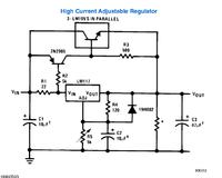
Note A tells you that the circuit must have a load of at least 30mA. If the normal load is less than this figure then that resistor should have a value which ensures it draws enough current to make up the difference between the load's current and 30mA.

e.g. if the load current was, say, 20mA, the value of the resistance should be such that it draws at least 10mA.

OK, I get it now - thanks.

I was not reading that note as the entire circuit should draw a minimum of 30mA from the voltage and that that resistor should draw any difference between the load and 30mA.

I was actually reading as that resistor should draw a minimum of 30mA and I could not understand what purpose that would have.

I presume that below 30mA the voltage regulator has trouble regulating the voltage?
 

Yes, that's correct.

I am still a little confused by this regulator circuit.

Does the resistor labelled "see note a' represent and additional resistor to what ever circuit you are driving from this regulator circuit?

Or does it represent the actual circuit you are driving from this regulator circuit?
 

If the circuit which the regulator supplies draw at least 30 mA then there is no need to include this resistor.

Only if the circuit drew less than 30mA would it be necessary to include the resistor.
 

If the circuit which the regulator supplies draw at least 30 mA then there is no need to include this resistor.

Only if the circuit drew less than 30mA would it be necessary to include the resistor.

Well in that case it is highly unlikely that I would need it.

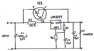
I get how the 2N2905/TIP73 combination is supposed to work from the ignition coil driver circuit we have been discussing in the other thread.

But I can't quite get my head around how the LM317/BC327 combination is supposed to work.

If the LM317 starts drawing more than usual current then we want to BC327 to start conducting which would turn on the big bypass transistor that supplies the additional current.

But BC327 is PNP and it is already in a conducting state while the LM317 is drawing a small current.

It is obviously got something to do with that 22R resistor but I can't quite see it.
 

But BC327 is PNP and it is already in a conducting state while the LM317 is drawing a small current.
Not true.
The PNP transistor is in non-conductive state for as long as the voltage across the 22 Ohm resistor is below 0.7V.

It is obviously got something to do with that 22R resistor but I can't quite see it.
You need at least 0.7V across it to "activate" the PNP ...

:wink:
IanP
 

Not true.
The PNP transistor is in non-conductive state for as long as the voltage across the 22 Ohm resistor is below 0.7V.


You need at least 0.7V across it to "activate" the PNP ...

:wink:
IanP

So I guess that would mean say 24V at the Vcc end of the 22R and 23.3V at the other end of the 22R.

I suppose the combination of the 22R and the LM317 + the rest of the circuit forms a voltage divider on the base of the BC327?
When the circuit hanging off the Lm317 is lightly loaded then that side of the voltage divider has high resistance and drops most of the voltage from Vcc.
As you add more devices to the LM317 circuit you generally do so in parallel such that the total resistance of that side of the voltage divider falls and it draws more current.
The proportion of Vcc dropped by the LM317 side of the voltage divider decreases while the proportion dropped by the 22R side increases until the differential across the 22R is large enough to provide a sufficient voltage drop across BC327 EB to allow current to start flowing.

Does all that sound about right?

Why 22R? How did they come up with that value? Trial and error with a bread board?
 
Last edited:

A = V / R
0.7 / 22 = 31mA. (it may be less than 0.7 volts)
It is 30mA current after which transistors will strat conducting. That is, the initial current is regulated by the I. Load resistor is used to avoid switching spikes and operate in linear region and not like a switching regulator.
By selecting 22 ohm resistance, it is posible to operate LM317 without a heat sink. With increased resistance, there may be a problem with stability and regulation accuracy.

OK let me get my head around this......

You saying that the innitial voltage drop across the 22R is 0.7V, so 24V at the Vcc end and 23.3V at the LM317 end......because that is the voltage drop across the CE circuit in the BC327. This situation is similar to the current limter I am playing with where 2 x 1n4148 are used in parallel with a sense resistor to fix a voltage drop across it of 0.7V. So that causes a current of about 30mA to trickle into the LM317 even if there is a very small load attached to it that would draw less than 30mA or no load at all.

So by keeping the LM317 conducting a small amount of current, regardless of load conditions, you avoid an in rush current similar to what you get when you pressurise a garden hose and then suddenly open up the nozzle.

Is this what you are saying here?
 

As PNP power transistors are more difficult to get, in this circuit a NPN power transistor is used as a solution. The gain of the two transistor multiply and a very small variation in input current causes a large response in output and a tendency of oscillation.
Have a look on other circuits around.
From page
http://www.siliconchip.com.au/cms/A_100994/article.html
1285601400_1351610131.jpg


8068855700_1351610304.jpg


And this one like yours requiring a load

**broken link removed**


Why let it go when LM317 can handle 1.5A
5695305200_1351612649.jpg
 
Last edited:

I appear to have had some success.

Starting with the original circuit in the LM317 datasheet, I substituted the 2N2905.... with BC327, re-calculated its base transistor value and substituted the TIP73 with a 2SD2498 from an old tv.

It seems to work just fine. With a 12V/0.21A fan from an old PC power supply as a load, the tv power transistor was warming up and, measuring the current, I am getting some where around 900mA being supplied to the fan through this tv transistor. I suspect the fan wouldn't last too long if I supplied it with 900mA plus for an extended period of time - they don't seem to spin that fast in a PC power supply.

So that is rather encouraging!

I probably don't really need it but, as an exercise I am going to incorporate that current limiting circuit into the out put of the tv transistor to make sure its current limit is never exceeded.

With more current available perhaps my mosfet gate driver IC will drive my mosfet a little more efficiently.
 
Last edited:

Hi,
Sorry to wake an old-ish thread but I wanted to check something.
In the first schematic on the page, would the 22 ohm resistor have to be matched to whatever your current was? If you had a 15v input and the full 1.5a across the voltage regulator, would the resistor have to be rated at 22.5w or above?

I got that circuit from the datasheet and, as I understand it, that 22R resistor form a voltage divider with the LM317.

At low current the LM317 drops the vast majority of the voltage and the 22R very little hence the 2N2095 remains off.

But as the current draw through the LM317 increases the 22R starts to drop more voltage resulting in a lower voltage at the LM317 input terminal.

That causes the 2N2095 to start turning on since there is a sufficient voltage differential between its emitter and the LM317 input terminal.

But all in all the voltage drop across the 22R remains quite small even though the current through it might be 1A or so.

I would have thought a 2-5W metal oxide resistor would be more than enough for a wide range of input voltages.

I believe you can fiddle around with the value a bit to vary the LM317 thorough current at which the pass transistors start to kick in.

There are no formulas in the datasheet so I guess it is a matter of experimentation.
 

Status
Not open for further replies.

Part and Inventory Search

Welcome to EDABoard.com

Sponsor

Back
Top