Continue to Site

Welcome to EDAboard.com

Welcome to our site! EDAboard.com is an international Electronics Discussion Forum focused on EDA software, circuits, schematics, books, theory, papers, asic, pld, 8051, DSP, Network, RF, Analog Design, PCB, Service Manuals... and a whole lot more! To participate you need to register. Registration is free. Click here to register now.

LM317 current limit circuit blew up

Status
Not open for further replies.

Xenobius

Member level 5
Member level 5
Joined
Feb 25, 2019
Messages
84
Helped
0
Reputation
0
Reaction score
0
Trophy points
6
Activity points
850
Hi all,

I have several current limit circuits for several LEDs. In another post on this forum we have been through the voltage, led rating, binning of leds and whatnot. I did build the circuit and it worked flawlessly so I moved on to the final version of the circuit. However stupidly enough I added a diode without testing it. I believe I was reading somewhere and it said you always should have a diode!

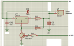
So here is the circuit - I have a transistor which pulls the ADJ of the LM317 down to ground and effectively killing the lights out. When tested (without the diode) it worked flawlessly as said already however with the diode, the transistor (s) just blew up! I have yet to repair and remove the diode and try again but my question is - what on earth happened? I am attaching the circuit.

1 important thing to note is that actually when the micro controller signal was OFF, the transistor was off, and the leds where nice and bright without issues!
the moment the micro controller started to PWM the transistor (which again worked well without the diode earlier) the transistors just blew up.

Why did this happen? Thank you all :)
 

Attachments

  • led limit ccy.png
    led limit ccy.png
    34.6 KB · Views: 335

1) why did you use a Schottky diode for this? It has terrible leakage current. A standard rectifier should be used, just like the data sheet shows.
2) Without knowing the full details of the internal circuit of the LM317 it’s hard to say, but my guess is that when you pull ADJ low, the output cap discharges through the diode into your transistor. The block diagram shows a current source in that path, but who knows what that really is?
3) I’m not convinced that pulling ADJ to ground is a good thing, with or without a diode.
 

This circuit is not properly implemented.
Where is R2 and how do you adjust the Output Voltage when the Transistor is OFF ??
Why is Schottky diode ?? A standard 1NXX diode is adequate..
 

1) why did you use a Schottky diode for this? It has terrible leakage current. A standard rectifier should be used, just like the data sheet shows.
2) Without knowing the full details of the internal circuit of the LM317 it’s hard to say, but my guess is that when you pull ADJ low, the output cap discharges through the diode into your transistor. The block diagram shows a current source in that path, but who knows what that really is?
3) I’m not convinced that pulling ADJ to ground is a good thing, with or without a diode.
Why Schottky? I have absolutely no clue. Clearly its wrong.

I only covered parts of the circuit which are replicated as i have 20x of these

Where is R2? Its somewhere else on the circuit which drives the microcontroller.
 

My guess is slightly different: driving PWM into the transistor isn't a problem, pulsing almost 30V at around 0.5A across C5 probably made it look like a short circuit as a load.

The diode probably isn't necessary at all if C5 is removed, it's purpose it to make sure the output voltage at 'VO' doesn't go above the input voltage at 'VI' bit if C5 is removed that can't happen anyway.

If you really want to average the PWM back to an analog voltage, a capacitor across the transistor C and E is probably better and it can be a much lower value, however any averaging will dramatically reduce the circuits efficiency. PWM at 'faster than perception' speed is most efficient as long as the LM317 can handle the switching frequency.

Brian.
 
Thanks Betwixt - in all fairness when I did the trial, C5 and D3 where not included and it worked perfectly. I only added them after further reading without actually trying it. I believe this is an easy fix - just remove them and repair the broken transistors. I will let you know how it goes. Thanks a lot for now.
 

Any clues like Q3 E-C short, B-E or B-C short ? Or opens ?


Regards, Dana.
 

I agree with betwixt, the problem is C5, not the diode. Look at LM317 datasheet

1595713753626.png


You see that Q3 discharges C5 through the 6V zener diode and a 50 ohm resistor, possibly damaging Q3 as well as LM317.
 

    Easy peasy

    Points: 2
    Helpful Answer Positive Rating
Based on the above schematic of the lm317, this discharge problem exists without the diode. Again, I question the validity of pulling the ADJ pin to ground. BUT, this all begs the question: what are you trying to do here? A PWM‘d current limiter??? If you’re trying to generate a PWM-controlled voltage, why do you need the LM317? If you’re trying to limit current with the LM317, why do you need PWM??
 

An LM317 has a slow response time and is not really suitable for PWM.
For PWM, just use a MOSFET as a switch.
 

Hi so I am trying to control 3W LEDs that have a voltage drop of 3.2 to 3.6v and a max of 800mA. I am using LM317 to limit the current.

I have 7 leds in series potentially 7x 3.6v = 25.2v
LM317 needs 1.25V + 3V
Total voltage 29.45V hence the 30V input
 

Hi,

To limit the current: use a simple resistor. Or where do you see the benefit in a LM317 circuit?
To PWM: use a logic level Mosfet.

Most simple, reliable, low cost...

Klaus
 
As far as understand, the purpose of LM317 is to achieve constant LED current independent of supply voltage. With C5 removed, the circuit should basically work, despite of limited LM317 speed.

The circuit can be improved by implementing linear pwm current control, but I'm not sure if it's actually required.
 

Hi,

Yes, constant current is useful if load (voltage) or supply voltage varies.

I don't understand why PWM.
It still is a linear regulation, thus PWM has no efficiency benefit against linear current reduction.
It just causes flicker (maybe not noticable)and EMI...

Klaus
 

PWM fundamental to controlling brightness.

When PWM is high in this circuit LM317 V drops to Vref and regulates
that V while PMW high. Shuts off LED chain.

When PWM goes low LM317 enters, due to its fdbk from Isense R, constant
current mode. That fixes the current in the chain, and has a side benefit
that most LEDs, all operating off same current have equal brightness. This
is not exact because quantum efficiency led to led varies, but is a reasonable
compromise.

The PWM duty cycle effectively is controlling brightness due to avg current
proportional to duty cycle. PWM running fast enough no flicker, and there is
a persistence factor associated with eye response, eg. eye integrates
light level per se.


And as you stated eliminates brightness variation due to power supply variation.
That in turn means power does not have to be regulated, saving cost.


Regfards, Dana.
 

The original ckt ( post #1 ) appears to be wrong - you need a lot more Cin on the LM317 - they show a tendency to fail if the input has lots of ripple.
The Lm317 needs at least 2v5 of headroom - so for 29.5 Vout you need at least 32V in ...
FvM has also pointed out a failure mode that results from not reading the data sheet.
 
Last edited:
The original ckt ( post #1 ) appears to be wrong - you need a lot more Cin on the LM317 - they show a tendency to fail if the input has lots of ripple.
The Lm317 needs at least 2v5 of headroom - so for 29.5 Vout you need at least 32V in ...
FvM has also pointed out a failure mode that results from not reading the data sheet.

Hi, ok so I have regulated 30V power supply which I can fine tune to go up to 33v if I wanted to so really its just a small turn of a pot away from 33v. Now that you mention ripple (or someone else did) I feel like monitoring the output of the power supply to see how clean it is!

As for headroom, this is taken into consideration as in my previous post, the LM317 needs 1.25v to function and 3v headroom.
My leds need anywhere from 3.2V to 3.6V to function so if we take worse case scenario:

Worse case: 7 leds x 3.6V = 25.2V + 1.25 + 3 = 29.45V
Best case: 7 leds x 3.2V = 22.4V + 1.25 + 3 = 26.65V

As for "why the PWM" I need to control the LED brightness using a micro controller and as in my initial post, when I tried the circuit that I posted on a breadboard (without diode and capacitor) it worked perfectly without issues. Further reading of the datasheet (I think it was the datasheet) resulted that I needed the diode and the capacitor and to me it seams pretty harmless so I just built the final board with the diode and capacitor included without testing - this is stupid I know now however its just a matter of unsoldering them and I am back to the original circuit.

As for PWM speed and LM317 not being able to cope - I am not sure myself however the arduino pins I am using function at 490hz. I will try to understand from the datasheet if this is slow enough for the LM317 to cope or not.

Thanks for all the input so far.
 

I'd suggest a pragmatic approach. Remove C5 and check if the circuit is behaving according to your needs.
 

    Xenobius

    Points: 2
    Helpful Answer Positive Rating
If you look at LM317 load transient response your 2 ms rate is the
dominant system characteristic. The 317 is more than capable of
handling that.

1595851014562.png


Regards, Dana.
 

    Xenobius

    Points: 2
    Helpful Answer Positive Rating
Status
Not open for further replies.

Similar threads

Part and Inventory Search

Welcome to EDABoard.com

Sponsor

Back
Top