aneesh.r
Newbie

Hello,
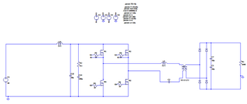
I am trying to build a DC-DC Converter Circuit. The input is 50V, 10A. The required output at 1250V, 0.8A. The output power is 1000W. After multiple design iterations, I arrived at LLC Topology for the converter. An efficiency > 85% is required practically. Hence, LLC was the suitable option.
The converter is designed in the following stages:
The increase in phase shift, has to increase the output voltage, due to increase in power transfer cycle.
This circuit was rigged up and PCBs were fabricated for testing.
The following are the observations:
Can the above questions be answered?
I am trying to build a DC-DC Converter Circuit. The input is 50V, 10A. The required output at 1250V, 0.8A. The output power is 1000W. After multiple design iterations, I arrived at LLC Topology for the converter. An efficiency > 85% is required practically. Hence, LLC was the suitable option.
The converter is designed in the following stages:
- Input Filter: An LC circuit with a 10uH Inductor and 120uF capacitor.
- Full Bridge Inverter: MOSFETs were operated with Phase Shifted gate pulses approach. AUIRFP4568 from Infineon were chosen as the MOSFETs which has Vdss = 150V.
- LLC Resonant Tank: The Resonant Capacitor was chosen to be 0.25uF. Film type capacitor was used for this purpose. The inductors were incorporated into the transformer.
- Transformer: A custom-made transformer was used. The leakage inductance between Prim-Sec, 10uH, played the role of the resonant inductor. The mutual inductance is 40uH. Turns Ratio is 1:6 (11 turns on Primary, 68 turns on Secondary).
- Full Bridge Rectifier: Diodes, C6D10170H, Silicon Carbide Schottky diodes were chosen. Vdc = 1700V
- Output Filter: Two 10uF capacitors connected in series is used.
The increase in phase shift, has to increase the output voltage, due to increase in power transfer cycle.
This circuit was rigged up and PCBs were fabricated for testing.
The following are the observations:
- The output at the full bridge inverter needs to be a switching waveform between -50V and +50V. But when the output was observed in the CRO, there were a few missing pulses (Image attached). What could be the reason behind this?
- Is the incorporation of the LLC Resonant tank inside the transformer a good approach?
- Since different outputs are required at different load values, is LLC an acceptable topology for this converter? This question is for the fact that in an LLC Topology the output is load dependent due to the reason that frequency changes with change in load.
- For lower load values, the output voltage trend was almost linear, with increase in phase shifts. For higher loads and higher phase shifts, the trend rose drastically. Is it regular in such converters?
- When an input of 50V is given, the gate waveforms experienced a lot of ringing. RC Snubber was introduced to the circuit to reduce the ringing, but there was no significant outcome from this. What is an alternative option?
- The MOSFETs in the full bridge are driven by UCC21521 gate driver IC which is placed external to the Primary PCB. Jumper wires were used for the interconnection. Is this a good approach?
Can the above questions be answered?


