LLC DC-DC
- Thread starter Pixelx
- Start date


- Joined
- Apr 1, 2011
- Messages
- 15,828
- Helped
- 2,918
- Reputation
- 5,850
- Reaction score
- 3,077
- Trophy points
- 1,393
- Location
- Minneapolis, Minnesota, USA
- Activity points
- 118,535
I think without the extra L & C, the transformer would need to be greater Henries (more windings) and thicker wire( more bulk) in order to shape square waveforms to sine. Suddenly we're talking about unnecessarily large power, due to a seeming paradox about the nature of inductance.
So the extra L & C is inserted to change the operating frequency while converting square waves to sine waves while using the smaller transformer.
So the extra L & C is inserted to change the operating frequency while converting square waves to sine waves while using the smaller transformer.
Easy peasy
Advanced Member level 6

You have to consider at least two situations:
shorted load; here the res freq is found from Lr & Cr - i.e. just leakage in the Tx and the Cres
in your case, apparently ~130uH total and 22nF => 94 kHz
if you run at this freq with a shorted load the currents will soon blow everything up - so your control must go higher than this ( at least 130kHz ) to limit the current in the output rectifiers,
similarly for no load volts, the freq must go high to limit max Vout @ no load.
Now let us consider full load - say 30V and 30A on the output - 900W
Lleak and Lmag form a divider - Lmag is further reduced by the load, ( we only know from your data that the turns ratio is 2.9 : 1 +1, we don't know the actual load )
So 30A in the sec is 10.3A on the driving ( pri ) side.
so the 22nF cap will have - at 80kHz say - 931 Vac across it - 1317V pk @ 10.3 A ac through it.
straight away this looks like a disaster - unless you have the right caps
We need 87 volts across the Lmag of the transformer + more volts to overcome the leakage ( which voltage is Z 80kHz ( 130uH ) x 10.3 ) = 673V ac = 952V pk.
and these ( Cr & Lr ) are 90 deg out of phase.
So the total driving voltage looks to be needing to be quite high unless we are close to the lower resonance at full power
The Lmag is 590uH in parallel with the load, here 1 ohm on the sec side ( 30V 30A ) = 8.5 ohm on the pri side -
reducing the transformer to 8.5 ohm in parallel with Xlmag of 65 ohm ( 80kHz ), with the essentially series Lleak of 130uH
The Q of the power circuit is now 2.pi.F.Llk / Rseries = 7.7 which is kinda OK
however since X Lmag is almost completely shorted by the load - 8.5 ohm in // with 65 ohm XL = ~ 7.51 ohm
the freq will not be a lot lower than 94kHz for full power - we have assume 80kHz which may well be close - assuming the load is 900 watt - we don't know - you didn't say.
for lighter loads the Lmag is not so shorted out by the load and there is more of it's inductance in play - providing an inductive divider - and therefore a lower freq for the new lower " full " power.
Always check your values for Vmax across then at full power - and of course work out the currents to see if the ESR is OK
p.s. at no load we have 590uH + 130uH and 22nF, this is 40kHz for resonance - so we want to be well above this for no load
at 130kHz, say the no load Vout out will be approx Vdrive/2 x 590/ ( 720 ) x 1/2.9 = 14V ac = 20 V peak rectified, for 100V on the totem pole.
Just so you are fully aware - lighter loads = higher freq for the LLC, increased load = control loop pulling the freq down towards resonance for increased power to the load for the same Vout, ( load resistance falling ).
happy designing @Pixelx
Last edited:
cupoftea
Advanced Member level 6
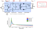
Here is LLC sim for you in LTspice.
Plus design doc.
Plus design doc.
| The calculations use the equations seen on pages 2 & 3 of AN-4151 by Fairchildsemi.com AN-4151 is prob the best beginner guide to LLC design. with LLC, it behaves just like a "standard transformer" when operated on load at the upper resonant frequency. ie Vs/Vp = Ns/Np. Remember that if you do half bridge LLC, then you vin is actually your input bus volts divided by 2. The lower resonant frequency is that frequency below which you must not go. Or else severe reverse recovery ensues. Also, you need to plot Vout vs freq for your design...locate the peak of this curve, you must not operate to the left of peak...ie no lower in freq. You will enjoy the LLC most if you are lucky enough to have a fixed vin and vout....because then you can get very low off and on sw losses. |
Attachments
Last edited:
Pixelx
Member level 3
Thank you for your answers. I will probably ask again. Currently analyzing AN-4151.
1. How to determine the coefficient before sin (attachment below)?
Preferably on integral calculus step by step. I checked the current value on the resistor in the simulation and this coefficient before sin gives the value of the sin amplitude. I would like to understand where this comes from. How to derive it?
Same with VRI.
2. Do LLC transformers have an air gap? If so, why are the windings coupled together in the same direction? (dots on the winding). FlyBack stores energy. And I don't see how to collect it because the diodes on the secondary side are directed towards conduction.
3. The following formula applies to a half bridge converter. I know its derivation. However, I do not understand why in LLC there is a transformer ratio in the numerator and the denominator is the number 2 and not 4
Attachments
cupoftea
Advanced Member level 6
Sometimes LLC has an air gap...when you use integrated transformer and you want to fix your value of leakage inductance (resonant inductance)..AN-4151 tells of it.
AN4151
The derivation for LLC uses the FHA (first harmonic approxiamation)...and then they just consider the power wave input to the LLC converter as a sine wave at the fundamental frequency. Very good of you to go through derivation....to design LLC, you dont have to do that...just number crunch those formulae and shove it in a sim to check.
AN4151
AN-4151 PDF
Part #: AN-4151. Description: Half-bridge LLC Resonant Converter. File Size: 1277.55 Kbytes. Manufacturer: Fairchild Semiconductor.
www.alldatasheet.com
The derivation for LLC uses the FHA (first harmonic approxiamation)...and then they just consider the power wave input to the LLC converter as a sine wave at the fundamental frequency. Very good of you to go through derivation....to design LLC, you dont have to do that...just number crunch those formulae and shove it in a sim to check.
- Joined
- Jan 22, 2008
- Messages
- 53,719
- Helped
- 14,812
- Reputation
- 29,921
- Reaction score
- 14,449
- Trophy points
- 1,393
- Location
- Bochum, Germany
- Activity points
- 303,688
LLC with integrated transformer needs an airgap to set Lp for resonant operation. This has nothing to do with flyback.2. Do LLC transformers have an air gap? If so, why are the windings coupled together in the same direction? (dots on the winding). FlyBack stores energy. And I don't see how to collect it because the diodes on the secondary side are directed towards conduction.
Pixelx
Member level 3
Very good of you to go through derivation....to design LLC, you dont have to do that.
I just want to understand exactly where these derivations come from. I feel more confident.
Would you be able to show how to derive this? These coefficients before sin and RFI?
Similarly with the formula for the number of turns N. I would like to understand why.
cupoftea
Advanced Member level 6
It comes out of the Fourier Transform of a square wave, and how to get the coefficients that all the harmonics are multiplied by.
In LLC, you only consider the first harmonic.
So the actual input to the LLC bridge is a square wave...but you just derive your first harmonic of that square wave (which is obviously a sine wave) , and then consider that as your excitation wave.
In LLC, you only consider the first harmonic.
So the actual input to the LLC bridge is a square wave...but you just derive your first harmonic of that square wave (which is obviously a sine wave) , and then consider that as your excitation wave.
Pixelx
Member level 3
Let me understand it better.
The smaller Ro --> the smaller Rac --> lower Q (e.g Q=0.25). The lower Q (e.g. 0.25), the greater the sinus amplitude.
With an LC circuit, the larger the Q, the more selective the resonant system is at a given frequency - the steeper it is.
In LLC, the smaller Q, the steeper the resonance system.
The smaller Ro --> the smaller Rac --> lower Q (e.g Q=0.25). The lower Q (e.g. 0.25), the greater the sinus amplitude.
With an LC circuit, the larger the Q, the more selective the resonant system is at a given frequency - the steeper it is.
In LLC, the smaller Q, the steeper the resonance system.
Attachments
Last edited:
cupoftea
Advanced Member level 6
In Post #4 i gave you the LLC design template , and the corresponding LLC simulation.
Concentrate first on this....it will be better for you.....set yourself a power supply spec and deign it and adjust the Lr and Cr etc until you get a nice fit.
Adjust also the Lmag and see the effect that it has..
So you must plot the Vout vs Freq graph....and then change the Lr and Cr etc , and you will soon see how to change things to achieve a certain spec.
The sim will show it all up for you.
Eg if you are not at the upper res freq when on full load then you will soon see on the sim that you arent getting the switching losses down as low as you otherwise could.
When you do the design, you may see that your upper resonant frequency is too close to the peak of the vout vs freq graph.......and so you must redesign so that you are away from the peak......because if your switching frequency goes to the left of the peak, then you will be in trouble....as vout goes down with lowering freq when below the peak.
If you pick a Cr too low, and an Lr too high, then you will get super high voltage on your Cr and so you will need to adjust away from this.....you will only see it if you do the design, and go through the vout vs freq graph...the equns are all given in the AN-4151.
When you look at the sim you will see the effect of dead time......you could do a perfect design, but if you get the dead time too short it will be rubbish.
Last edited:
Pixelx
Member level 3
Pixelx
Member level 3
I derived all formulas except one
The mathematical formula I added in the attachment in the previous post - I don't really know how to get started. Do you know where to start?
Another issue
,,The operating range of the LLC resonant converter is limited by the peak gain (attainable maximum gain), which is indicated with „*‟ in Figure 7. It should be noted that the peak voltage gain does not occur at fo nor fp. The peak gain frequency where the peak gain is obtained exists between fp and fo, as shown in Figure 7,,
does LLC work on GAIN greater than 1? Changing the frequency changes the gain-frequency characteristics
Pixelx
Member level 3
Sometimes LLC has an air gap...when you use integrated transformer and you want to fix your value of leakage inductance (resonant inductance)..AN-4151 tells of it.
What does integrated transformer mean?
Integrated that has leakage inductance and is divided into two parts? The transformer I sent in attachment will not have an air gap?
If so, the Excel sheet you sent concerns a different type of transformer? No integrated?
From what I saw, in Excel you use the equation I marked in red in the box.
And for an integrated transformer that has two windings separated (as I understand it at the moment), should we use the 2nd pattern that I marked in green?
Attachments
- Joined
- Jan 22, 2008
- Messages
- 53,719
- Helped
- 14,812
- Reputation
- 29,921
- Reaction score
- 14,449
- Trophy points
- 1,393
- Location
- Bochum, Germany
- Activity points
- 303,688
Latest post sounds confused provided you have been reading AN-4151, or any other LLC tutorial.
An integrated transformer implements both parallel and series inductance required for LLC operation in one component. As detailed described in AN-4151, parallel ("magnetizing") inductance is set by core permeability and air gap, series (leakage) inductance by separation between primary and secondary winding.
Looking at AN-4151 Lp versus air gap table, it's unlikely that you get good LLC performance without an air gap. I can't see if your transformer has an air gap in the center leg.
--- Updated ---
A wide range of shown AN-4151 curves exposes gain above 1, isn't it?does LLC work on GAIN greater than 1?
Pixelx
Member level 3
An integrated transformer implements both parallel and series inductance required for LLC operation in one component
1. A traditional transformer has two primary and secondary windings. The primary is wound with wire and is the magnetization inductance. This also includes the leakage inductance after the secondary side is short-circuited.
The schematic presented in LLC do not reflect the actual transformer because they show two windings wound in parallel.
You actually wind the primary and secondary and nothing parallel to it.
The leakage inductance itself is caused by poor magnetic coupling.
Could someone present the transformer designs according to article AN4151 - Consideration for IntegratedTransformerand the structure of the transformer to which you added the calculator.
2. I disassembled the transformer and it has an air gap, does this mean that the calculator sent above has an error because it does not take into Mv?
What does a transformer without a gap look like and is it for LLC? Does it have an additional coil Lr outside the circuit?
3. Is there a formula to calculate the estimated LLC core power?
Is this done experimentally to obtain an estimated ratio of Lr to Lm?
This is above 1, but when does 1 enter into it during transients? The article talks about a reserve of 10%-20%A wide range of shown AN-4151 curves exposes gain above 1, isn't it?
Attachments
Last edited:
- Joined
- Jan 22, 2008
- Messages
- 53,719
- Helped
- 14,812
- Reputation
- 29,921
- Reaction score
- 14,449
- Trophy points
- 1,393
- Location
- Bochum, Germany
- Activity points
- 303,688
1. I understand that you have problems to relate physical transformer design (e.g. one primary and one secondary winding) with equivalent circuit showing separate ideal transformer with winding ratio ("n:1") and Lkp, Lks, Lm elements representing the inductance. But that's the usual way to analyze transformers in text books, not only LLC transformers.
2. Question regarding Excel template must be answered by the author. I notice that PQ3230 core is specified with AL = 630 nH/n², means that it has an air gap, because ungapped core shows much higher AL.
PQ3230 AL:

2. Question regarding Excel template must be answered by the author. I notice that PQ3230 core is specified with AL = 630 nH/n², means that it has an air gap, because ungapped core shows much higher AL.
--- Updated ---
PQ3230 AL:
Last edited:
Similar threads
-
-
-
-
Issue with MAX17502H DC-DC Converter – 3.3 V Output Not Regulating at 5 V Input
- Started by akshayakumar
- Replies: 2
-