Pixelx
Junior Member level 3

Hello
I'm trying to understand how an LLC works. I even found such a converter and analyzed the waveforms on an oscilloscope on my own.
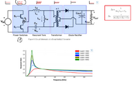
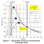
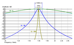
I found on the Internet that the resonance decreases with the load (photo below).
I don't understand why there should be a larger amplitude and greater resonance at a small load. Logically, Q should be higher when under heavy load. This means that the Q of the system decreases with the load.
There are two formulas to determine the resonance - the higher the load, the Lm decreases and the frequency changes to a higher one.
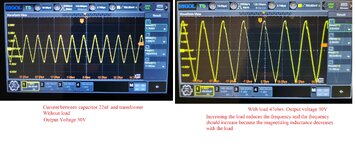
In the converter I tested, the frequency decreased with the load and the current amplitude increased.
I showed it in the photos below.
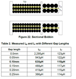
Parameters of the transformer from the converter I tested
L primary = 590uH
L leakage_primary - secondary side short circuit = 130uH
L secondary = 70uH
L leakage_secondary - primary side short circuit = 10uH
Capacitor 22nF
IC L6699
Attachments
Last edited:
