Continue to Site

Welcome to EDAboard.com

Welcome to our site! EDAboard.com is an international Electronics Discussion Forum focused on EDA software, circuits, schematics, books, theory, papers, asic, pld, 8051, DSP, Network, RF, Analog Design, PCB, Service Manuals... and a whole lot more! To participate you need to register. Registration is free. Click here to register now.

Light Fixture with DC Motor, AC to DC Inverter & Dimmer Switch

CB33

Newbie level 5
Newbie level 5
Joined
Aug 20, 2024
Messages
9
Helped
0
Reputation
0
Reaction score
0
Trophy points
1
Activity points
94
I have a technical question regarding a light fixture I'm building that also has a motor in it. I have geometric shapes that spin slowly around the light fixture light bulbs (almost like a mobile) and this is what I'm using the motor for. The light fixture will be attached to the ceiling like any normal light fixture or chandelier and I want to use a light switch on the wall to be able to turn it on and off. To power the light bulbs and the motor I am using an Inverter which is 12 Volt DC To 110 Volt AC. When you turn the light switch on both the light bulbs will turn on as well as the motor. The question I have is in regards to a dimmer switch. I want to use a dimmer switch to be able to make the lighter brighter or dimmer. However, because the motor is also being controlled by the dimmer switch I want to know if this will be a problem and what will happen. Will it slow down the rotation? Will It damage the motor? If it will pose a problem are there any simple solutions? The motor I'm using is a 12V Synchronous DC geared 1 RPM motor using AC power supply. Any insight or suggestion would be greatly appreciated.
Also, on a side note I'm not sure what inverter I should use for this project. The choice is between a constant current inverter/driver vs constant voltage inverter/driver. I'm not sure which one to use here. Thank you!
 
Hi,
Will it slow down the rotation? Will It damage the motor?
Your question is if dimmer and motor can work together.

BUT:
You give us no information about the dimmer type..
You give us no information about the motor type ... and how it is powered (circuit) ...

So we need a crystal ball to answer your question. I don´t have.

Klaus
 
..also..will the bulbs be dimmable (You write that you use 12v dc to 110v ac inverter for bulbs and motor)..? I'm thinking incandescent bulbs are dimmable but since they require way higher wattage/current it might be necessary to use led bulbs..while most "bulb" leds are not dimmable..
 
Hi,

Your question is if dimmer and motor can work together.

BUT:
You give us no information about the dimmer type..
You give us no information about the motor type ... and how it is powered (circuit) ...

So we need a crystal ball to answer your question. I don´t have.

Klaus

Hi Klaus. Thanks for your reply. Here is some additional information for this project

"You give us no information about the dimmer type.."
In terms of the dimmer, this is the one thing I haven't bought yet. I'm trying to figure out if it will work with one type of dimmer but not work with another. I can get any type of dimmer but need to know what I can and can't buy so open to suggestions here.

"You give us no information about the motor type ... and how it is powered (circuit) ..."
I just purchased a simple synchronous motor off of Amazon. Below is the link to the motor I'm using.

Hope this provided a little more insight into this. Thanks
 
..also..will the bulbs be dimmable (You write that you use 12v dc to 110v ac inverter for bulbs and motor)..? I'm thinking incandescent bulbs are dimmable but since they require way higher wattage/current it might be necessary to use led bulbs..while most "bulb" leds are not dimmable..
Just the motor is going to be powered by 12 V. The bulbs will be on 120 V so we can use incandascent bulbs. We are just using the inverter for the motor. Just the DC motor is on the 12 V. I am mainly doing this because getting UL approval becomes a big headache if I were to use an AC 110V motor in this light. Using a 12 V DC motor is kind of a loophole for me in order to get UL approval since it will not be a safety concern in terms of UL certification.
--- Updated ---

You know, they do make 12volt lights and 12volt motors...
I realize that but I want the lights at at 110 volt and the motor at 12v and that's why I have an AC DC inverter.
 
Last edited:
Oh..pardon me! ..I understood it the other way around..maybe a language barrier.. Anyway incandescents may not be available for very long time..where i live one can not buy them anymore at all..
 
Oh..pardon me! ..I understood it the other way around..maybe a language barrier.. Anyway incandescents may not be available for very long time..where i live one can not buy them anymore at all..
Sorry, I should clarify also. It can be incandescents or LEDs but I just mean I don't need specific low wattage 12V bulbs. I can use normal everyday light bulbs because only the motor is on DC but the lightbulbs will be on AC.
 
Sorry, I should clarify also. It can be incandescents or LEDs but I just mean I don't need specific low wattage 12V bulbs. I can use normal everyday light bulbs because only the motor is on DC but the lightbulbs will be on AC.
I STILL don't understand why on earth you would add the cost, complexity and added danger of converting 12V to 120V. You say you don't "need" 12V bulbs, but you certainly don't need 120V bulbs.

If you're concerned about UL approval, then, again, WHY would you boost the intrinsically safe, 12V to 120V??? UL approval is not required for anything operating at less than 35V (if I remember correctly). It doesn't matter if your motor is 12V, you've still got 120V in your device.

This just makes zero sense to me.
Hi Barry
Thanks again for your response. I'm not building a standard or typical light here and I realize from a utilitarian standpoint it would be easier just to keep this all 12V. However, with this particular light this is not what I'm looking to do. This light has certain design elements we're hoping to achieve that involve movement around the light similar to that you would see on a hanging mobile. Initially I wanted to keep this entire light 110v AC and the motor I was going to use at first was 110V AC also. I am not able to get UL approval with an AC motor in this light. However, If I run a 12V DC motor on the light, UL will certify this light for me. This is why I want to use an AC DC converter hardwired into this light. I specifically don't want to use more specialized 12V low wattage bulbs for this light either. I want to be able to use normal standard bulbs. Hopefully this explains what I'm trying to do a bit further and makes some sense now.
 
The motor I'm using is a 12V Synchronous DC geared 1 RPM motor
"Synchronous motor" and "DC" is contradicting.

"Synchronous" means it´s RPM follow the AC frequency.
"DC" means zero Hz.

So if a synchronous motor is driven by 0Hz then the motor will rotate with 0 RPM. It stops.

It can not be 0 RPM and 1 RPM at the same time.

Klaus
 
Hi Barry
Thanks again for your response. I'm not building a standard or typical light here and I realize from a utilitarian standpoint it would be easier just to keep this all 12V. However, with this particular light this is not what I'm looking to do. This light has certain design elements we're hoping to achieve that involve movement around the light similar to that you would see on a hanging mobile. Initially I wanted to keep this entire light 110v AC and the motor I was going to use at first was 110V AC also. I am not able to get UL approval with an AC motor in this light. However, If I run a 12V DC motor on the light, UL will certify this light for me. This is why I want to use an AC DC converter hardwired into this light. I specifically don't want to use more specialized 12V low wattage bulbs for this light either. I want to be able to use normal standard bulbs. Hopefully this explains what I'm trying to do a bit further and makes some sense now.
Sorry, but I STILL don’t understand. Please answer this simple question:

1) If your source voltage is 12 volts, why can’t you use a 12V lamp?

12V lamps are not “specialized”; go to any auto parts store.

If you’re trying to develop a commercial product why add all the expense of an inverter? And, you do realize that your inverter will have to be UL approved, right? AND FCC approved.
1) "If your source voltage is 12 volts, why can’t you use a 12V lamp?"
My source voltage is not 12V it's 110V. This is a light for a house and like most North American houses the source voltage is 110V. We are just doing 12V for the motor for safety because the UL inspector recommended we use this for safety and to pass inspection.

2.) "12V lamps are not “specialized”; go to any auto parts store."
I'm not saying they're hard to get. They are not the "norm' for in house light fixtures which is what this is. It is a ceiling chandelier.

3.) "If you’re trying to develop a commercial product why add all the expense of an inverter? And, you do realize that your inverter will have to be UL approved, right? AND FCC approved."
I made a mistake on the terminology. I should be calling it a converter as opposed to an inverter. They are not that expensive and they will allow me to do what I want for this particular light. I realize that it has to be UL approved. The thing is I can buy these already UL approved very easily and they will pass inspection very easily being UL approved. I cannot by AC 110 V motors that run at 1 RPM and are UL approved. They simply don't exist. I can get a DC 12V motor that run at 1 rpm and it does not have to be UL approved because it is not a safety hazard.

Does that make sense now or should I clarify a bit further?
 
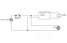
Here is a diagram of what I'm trying to do.
 

Attachments

  • Moto-Dimmer-Converter.png
    Moto-Dimmer-Converter.png
    13.1 KB · Views: 32
Here is a diagram of what I'm trying to do.
I have tried to be patient with you, but I am now giving up. I know it’s not a language barrier, since you obviously live in the U.S. Your very first post said:

“ To power the light bulbs and the motor I am using an Inverter which is 12 Volt DC To 110 Volt AC. “

Then you show a picture of a 110 volt to 12 volt “converter” (Which ALSO would need UL, and probably FCC, approval)

If you are incapable of clearly stating what you actually are trying to do, I can’t help you. I will leave it to others.
 
Now we see your original requirement from the first post and the diagram in post #14 it makes more sense.
No, you cannot do it that way, the lights will dim but the motor won't work and the 110V to 12V converter may be damaged.

The reason is that most dimmers use what we call "trailing edge" triggering, they reduce the lamp brightness not by controlling the voltage but for how long it is passed to the load (the lights). On each AC cycle the line voltage goes to a positive voltage peak of about 150V then passes through zero to a negative 150V peak then through zero again to the next positive peak. The "trailing edge" is the part of the cycle after the peak and before the zero crossing. The dimmer works like a fast acting switch, for maximum brightness it turns on at the peak and continues to conduct until zero is reached, for lower brightness, the switch on occurs later in the cycle so the voltage has dropped from its peak and also the conduction is for a shorter time. Overall, it gives the appearance of lower brightness.

There are two kinds of 110V to 12V converter, one uses an iron transformer, the other uses a fast switching system called "switch mode" or SMPS. If the chopped waveform goes to an iron transformer it causes all kinds of problems because they don't tolerate the sudden switching on, especially at peak voltage very well, they prefer the gradual rise and fall of a regular AC waveform. Usually they get excessively hot and make a buzzing sound but they can also damage the dimmer. The other kind of converter, the SMPS, has a completely different problem, firstly it needs some voltage to start working at all so setting the dimmer low might stop it altogether, they also have regulation built in to them so they will, as best as they can manage, fight against the changing dimmer output.

Regardless of the converter, it seems you are using a synchronous motor. They use a combination of windings and rotor design, sometimes a capacitor too, to produce a magnetic field that encircles the rotor (the moving part). As the AC voltage rises and falls, the magnetic field revolves and pulls the rotor around with it. If you run a synchronous motor on DC the magnetic field will be stationary and it will lock instead of turning. Note that a stalled motor, one that cannot turn will typically take up to 10 times its normal power and that would likely burn it out.

The solution to your problem is to wire the converter after the on/off part of the dimmer switch but before the dimming circuit so it sees full 110V all the time. Alternatively, use a different switch altogether to turn the power on and off and if necessary short out the switch in the dimmer so it thinks it is on all the time.

Brian.
 
I agree with KlausST that the motor specification (synchronous, 12V DC, 50/60 Hz) is a contradiction-in-terms. But no problem, if it runs smoothly off 12 V DC, it's probably what you want.

Don't recognize at first sight what's UL related the problem with a small 120V AC synchronous motor. Two requirements must be fulfilled, overcurrent/overtemperature protection (a small fuse) and electrical shock protection, motor metal case must not be exposed or connected to PE (as for most AC powered lights with metal case).
 
Now we see your original requirement from the first post and the diagram in post #14 it makes more sense.
No, you cannot do it that way, the lights will dim but the motor won't work and the 110V to 12V converter may be damaged.

The reason is that most dimmers use what we call "trailing edge" triggering, they reduce the lamp brightness not by controlling the voltage but for how long it is passed to the load (the lights). On each AC cycle the line voltage goes to a positive voltage peak of about 150V then passes through zero to a negative 150V peak then through zero again to the next positive peak. The "trailing edge" is the part of the cycle after the peak and before the zero crossing. The dimmer works like a fast acting switch, for maximum brightness it turns on at the peak and continues to conduct until zero is reached, for lower brightness, the switch on occurs later in the cycle so the voltage has dropped from its peak and also the conduction is for a shorter time. Overall, it gives the appearance of lower brightness.

There are two kinds of 110V to 12V converter, one uses an iron transformer, the other uses a fast switching system called "switch mode" or SMPS. If the chopped waveform goes to an iron transformer it causes all kinds of problems because they don't tolerate the sudden switching on, especially at peak voltage very well, they prefer the gradual rise and fall of a regular AC waveform. Usually they get excessively hot and make a buzzing sound but they can also damage the dimmer. The other kind of converter, the SMPS, has a completely different problem, firstly it needs some voltage to start working at all so setting the dimmer low might stop it altogether, they also have regulation built in to them so they will, as best as they can manage, fight against the changing dimmer output.

Regardless of the converter, it seems you are using a synchronous motor. They use a combination of windings and rotor design, sometimes a capacitor too, to produce a magnetic field that encircles the rotor (the moving part). As the AC voltage rises and falls, the magnetic field revolves and pulls the rotor around with it. If you run a synchronous motor on DC the magnetic field will be stationary and it will lock instead of turning. Note that a stalled motor, one that cannot turn will typically take up to 10 times its normal power and that would likely burn it out.

The solution to your problem is to wire the converter after the on/off part of the dimmer switch but before the dimming circuit so it sees full 110V all the time. Alternatively, use a different switch altogether to turn the power on and off and if necessary short out the switch in the dimmer so it thinks it is on all the time.

Brian.
Thanks for your reply. It's a good solution but I can't unfortunately we're limited because we're dealing with basic household wiring that we can't change since it's in the wall.
 
There is a solution, I use something similar here for lighting control (without a motor in my case) but you probably wont like it. My lighting is controlled by WiFi, using a tiny $2 MCU in the wall box and another in the light fittings. It allows for a second 'data' channel to control the brightness, independently of the AC feed. I use it because several light fittings can be controlled from one knob and as a 24/7 carer for someone with a disability, it is important that low brightness lighting is on overnight without affecting sleep too much. Basically, the brightness control is read and a number is sent by WiFi to identify the target light fitting followed by a number to set the dimming level.

Brian.
Thanks for this idea. It's actually a great idea and I didn't even realize this was a possibility. It's still a bit of an issue though because someone would have to go in the wall to accommodate having this light. I'm looking to try and avoid this and want to have it so no additional electrical work will have to be done if someone were to get this fixture. I'm hoping to find a solution where the light can get installed in the ceiling and won't require any special electrical work to have this light.
 

LaTeX Commands Quick-Menu:

Similar threads

Part and Inventory Search

Welcome to EDABoard.com

Sponsor

Back
Top