Vermes
Advanced Member level 4

From this article you can learn how to supply LEDs. Common problems with their connection, resistors calculation methods and sample applications will be discussed below.
Light produced by a LED:
One of the basic parameters of a LED (except the power) is kind of light generated by it. Electroluminescence LEDs are made of semi-conductive materials. Depending on the additive used, different hue can be obtained. The following picture shows how the range of colors varies according to the length of the electromagnetic wave.

Figure 1. The spectrum of white light
Colors of LEDs are often described using the wavelength it generates. Manufacturers catalogs usually consist of the following parameters of colors:
In the case of white LEDs, pay attention to the color of light they generate. The cheapest ones produce cold color >5000K, between 3500-5000K the color is neutral and <3500 it is warm.
Another parameters are the brightness of the LED measured in candelas (cd) and beam angle (degrees). Elements of too small beam angle will light up small surface.
LEDs supply:
LEDs are powered by direct current. Values of voltage and current should be selected accordingly to the type of LED. The following picture shows examples of a connection of several LEDs.

In order to calculate the value of resistor correctly, use Ohm's law (U=RI). The current flowing through the resistor is equal to the current of the LED and its value should be calculated so that the value of the tension accumulated on it was equal to the supply voltage minus the voltage of the LED. You should also know the basic values:
Resistor connected in series can be calculated using a simple formula which can be made from the Ohm's law:
R=(Us-Ud)/Id
where:
R – resistance of the resistor
Us – supply voltage
Ud – diode voltage
Id – diode current
When you have more than one LED (the same kind of LEDs) connected in series with a single resistor, then the sum of their voltages should be taken under account.
R=(Us-Udn)/Id
where:
Udn=Ud*n
n – the number of diodes
Calculated value should be rounded and you should choose the closest value of the series.
Connecting in parallel of few diodes is possible, but due to the eventual different currents flowing through the diodes such connection is not recommended.
In the case of a greater diode or their greater power, the power of resistor should be carefully selected. Calculations can be done using the following formula:
P=Ur*Id
where:
Ur – voltage on the resistor
Id – diode current
In the case of the resistor power, always choose a value one series greater than the number in the calculation.
Note! In the following examples there is 230V! Be careful and follow safety rules.
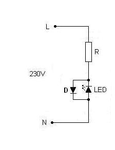
In a case of connecting a diode to 230V, calculate the calues of resistor identically as for direct current. The only difference is that you should add second rectifying diode connected antiparallel to the LED. It is intended to limit the reverse voltage (which causes damage to the LED). Sample connection is shown in the picture below:

You can also build a more complicated system with use of a rectifier bridge. Below picture shows such a solution:

The system allows you to eliminate the effect of „blinking” and greatly extends the life of a LED. Changing the capacitor C2, R3 and Zener diode ZD allows you to connect more LEDs.
Picture of a simpler system:

Values of the elements:
R1=510kohm
C1=0,47uF 275V MPX
Bridge of diodes IN4007
R2=36kohm
C2=4,7uF 400V (electrolytic)
R3=15ohm
One of the best systems powering the most LEDs uses a power supply with surge protection and a current source forcing a constant current value of the power transistor collector. Regardless of the number of LEDs connected in series, the value of current will always be equal 20mA.

High-power LEDs are nowadays very popular, they are often used in constructions of flashlights and headlights. LED control of that type diode is not as simple as an ordinary LED with a neglible current of 20mA. The use of a typical systemwith a serial resistor would result in increased losses. Manufacturers recommend the construction of a stabilized current source or purchase ready-made solution.
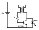
The system of white LED supply from a single battery:

Power diodes can be powered from a pulse inverter such as MC34063. Below there is one of the simplest applications of such a system:

The efficiency of this system can be more than 80%.
Common solutions are based on LM317 stabilizer, but they are less economical due to the bigger losses.
Light produced by a LED:
One of the basic parameters of a LED (except the power) is kind of light generated by it. Electroluminescence LEDs are made of semi-conductive materials. Depending on the additive used, different hue can be obtained. The following picture shows how the range of colors varies according to the length of the electromagnetic wave.

Figure 1. The spectrum of white light
Colors of LEDs are often described using the wavelength it generates. Manufacturers catalogs usually consist of the following parameters of colors:
- red – 626, 645nm
- orange – 605nm
- yellow – 590nm
- blue – 470nm
- green – 525, 572nm
In the case of white LEDs, pay attention to the color of light they generate. The cheapest ones produce cold color >5000K, between 3500-5000K the color is neutral and <3500 it is warm.
Another parameters are the brightness of the LED measured in candelas (cd) and beam angle (degrees). Elements of too small beam angle will light up small surface.
LEDs supply:
LEDs are powered by direct current. Values of voltage and current should be selected accordingly to the type of LED. The following picture shows examples of a connection of several LEDs.

- connected in series with a resistor and direct voltage
In order to calculate the value of resistor correctly, use Ohm's law (U=RI). The current flowing through the resistor is equal to the current of the LED and its value should be calculated so that the value of the tension accumulated on it was equal to the supply voltage minus the voltage of the LED. You should also know the basic values:
- LED current (usually it depends on the brightness: the brighter, the greater current, from few to several hundred mA)
- LED voltage (usually associated with the color)
- supply voltage
Resistor connected in series can be calculated using a simple formula which can be made from the Ohm's law:
R=(Us-Ud)/Id
where:
R – resistance of the resistor
Us – supply voltage
Ud – diode voltage
Id – diode current
When you have more than one LED (the same kind of LEDs) connected in series with a single resistor, then the sum of their voltages should be taken under account.
R=(Us-Udn)/Id
where:
Udn=Ud*n
n – the number of diodes
Calculated value should be rounded and you should choose the closest value of the series.
Connecting in parallel of few diodes is possible, but due to the eventual different currents flowing through the diodes such connection is not recommended.
In the case of a greater diode or their greater power, the power of resistor should be carefully selected. Calculations can be done using the following formula:
P=Ur*Id
where:
Ur – voltage on the resistor
Id – diode current
In the case of the resistor power, always choose a value one series greater than the number in the calculation.
- connected in series – 230V AC voltage:
Note! In the following examples there is 230V! Be careful and follow safety rules.
In a case of connecting a diode to 230V, calculate the calues of resistor identically as for direct current. The only difference is that you should add second rectifying diode connected antiparallel to the LED. It is intended to limit the reverse voltage (which causes damage to the LED). Sample connection is shown in the picture below:

You can also build a more complicated system with use of a rectifier bridge. Below picture shows such a solution:

The system allows you to eliminate the effect of „blinking” and greatly extends the life of a LED. Changing the capacitor C2, R3 and Zener diode ZD allows you to connect more LEDs.
Picture of a simpler system:
Values of the elements:
R1=510kohm
C1=0,47uF 275V MPX
Bridge of diodes IN4007
R2=36kohm
C2=4,7uF 400V (electrolytic)
R3=15ohm
One of the best systems powering the most LEDs uses a power supply with surge protection and a current source forcing a constant current value of the power transistor collector. Regardless of the number of LEDs connected in series, the value of current will always be equal 20mA.

- connected high-power LEDs:
High-power LEDs are nowadays very popular, they are often used in constructions of flashlights and headlights. LED control of that type diode is not as simple as an ordinary LED with a neglible current of 20mA. The use of a typical systemwith a serial resistor would result in increased losses. Manufacturers recommend the construction of a stabilized current source or purchase ready-made solution.
The system of white LED supply from a single battery:

Power diodes can be powered from a pulse inverter such as MC34063. Below there is one of the simplest applications of such a system:

The efficiency of this system can be more than 80%.
Common solutions are based on LM317 stabilizer, but they are less economical due to the bigger losses.
