Continue to Site

Welcome to EDAboard.com

Welcome to our site! EDAboard.com is an international Electronics Discussion Forum focused on EDA software, circuits, schematics, books, theory, papers, asic, pld, 8051, DSP, Network, RF, Analog Design, PCB, Service Manuals... and a whole lot more! To participate you need to register. Registration is free. Click here to register now.

led mosfet switching

Status
Not open for further replies.

mpiepen

Newbie level 2
Newbie level 2
Joined
Nov 20, 2017
Messages
2
Helped
0
Reputation
0
Reaction score
0
Trophy points
1
Activity points
24
Goodmorning,

I'm trying to light up a led with an old light barrier I still have around. I want the led to light up when someone passed the barrier. Unfortunately I have a 24v signal when the barrier is safe and when someone walks through it, the voltage drops to 0.

I still have some mosfets around but I’m not sure how to tackle this problem. I know I could use relay’s but I do not really have space for one. I have some mosfets and resistors so that shouldn’t be much of a problem.

Long story short: I’d like to make a 24v circuit with mosfets. When there is no signal my led should light up.

Is there a simple way to do it?
 

Hi,

first we need values.
Power supply: 24V DC or AC?
LED voltage:
LED current:

driving source:? what is it? Source impedance, high sdie, low side, push pull?

For calculating a resistor or a switching transistor circuit: there are numeruos examples in the internet. Only Ohm´s law.

Klaus
 
Hi mpiepen,

I couldn't understand your problem clearly,
But even though there are much compact relays available on market

A schematic diagram of your circuit will be good to clear out hurdles smoothly
 

Hi mpiepen,

I couldn't understand your problem clearly,
But even though there are much compact relays available on market

A schematic diagram of your circuit will be good to clear out hurdles smoothly


Hi, my led is 24v but I dont know about the current
My source voltage for the switch is 22v.

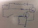
LEDsch.jpg

I've made a drawing but i'm not sure if it's correct.
 
Last edited by a moderator:

Hi mpiepen,

I think the circuit you've made is not correct, first of all the transistors polarity, the upper one should be NPN and... BJT? I don't think you have a 4 terminals BJT transistor.

How does the light barrier work? When there's an object between emitter and receiver it outputs... 24V?

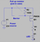
If so, the circuit should be much more easier, with a single transistor, just like this:
dasdasda.PNG


If the LED is 24V I assume it's an array of them in series, and they commonly come with its own limiter resistor (take a look at it), if not, you calculate it with the formula. Each white LED (I assume they are) drops about 3,6V, so do your maths, or measure it.
 
Hi,

I don't think the circuit does what the OP wants.

I've just re-read the whole thread.
So I assume the OP want's some inverting function.
When there is no signal my led should light up.
I assume "no signal" is the opposite to "24V"
--> 0V = LED ON.
Three points*
* one need to ensure a valid LOW level when there is not 24V
* one needs to limit V_GS on the mosfet
* the Mosfet should invert the function.

I'd use a P-Ch-mosfet. Source to 24V, drain to anode of LED
Rest: Cathode_of_LED - Rv - GND

Now that we don't know the exact dropout voltage when the output is "24V" and we don't know V_gs_th of the mosfet we need to calculate somehow conservative.
Worst case: dropout of 3V, threshold 1.5V.

Let's create a string of three resistors: 24V - R1 - R2 - R3 - GND
To limit current let's calculate with R3= 10k
Gate on the R1 - R2 node.
Barrier on the R2 - R3 node
If we now make R1 = R2 = 10k, too, then we ensure
V_GS = 1.5V when output = 21V (= 24V - 3V dropout) => LED OFF
V_GS = 8V when output = OPEN. => LED ON

All just assumptions....

Klaus
 
Oh yes, I read wrong. When someone passes through the barrier, it will put 0V as output. You could use a P-MOS as Klaus says.

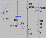
Another thing to keep in mind: If a person pass trough it, the signal will be 0V only when the light barrier is blocked, which is less than half a second at normal speed. You should put a timer (RC + diode) to keep the light turned on for a period of 40 seconds, to say. The circuit would be the following:

dasdasda.PNG


If yo want the timer feature, it is this one:
aaaaaaaaaaaaaaa.PNG.


Anyway it would be grat to get some more information about the electrical output of the light barrier such as impedance, maximum currents, real (not aproximate) values of voltage in both states and so. If it's like you say, 24V and 0V, both circuits should work fine.
 

Status
Not open for further replies.

Part and Inventory Search

Welcome to EDABoard.com

Sponsor

Back
Top