Vermes
Advanced Member level 4

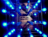
It is a project of LED cube 4x4x4. This cube is directly connected with the board without many cables when using an universal board. The knowledge, materials and the general idea to create such a cube can be taken from **broken link removed**.
The LED cube was made accordingly to the schema:

The schema differs from the original one:
- the programming connector was changed to 7 headers bar
- new 3 buttons (stop/start, switch, check) were added
- on/off switch was added
- the RS 232 communication was removed
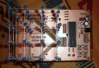
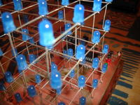
The project consists of 64 LEDs, combined in 4 layers of 16 LEDs, creating a cube in three dimensions. LEDs in the project were specially selected to be diffuse, so as to distract as much light as possible.
The main element of the system is Atmega16, clocked by an external quartz with a frequency of 14.7456 MHz. It controls the buttons, transistors, programming connector and LEDs. Atmega16 can at one time release the current of 200mA (note sheet), hence the choice of the value of 220ohm resistors, which in turn gives: 200mA/16 LEDs = 12,5mA per a LED. A satisfactory result, especially at night, was created in this way.
The system has 4 buttons for communication with user:
- reset (system reset)
- stop/start (stop/start of the sequence chosen)
- switch (choice of the sequence)
- checking the correctly uploaded code
After running the system, the boot sequence turns on, but before that, two control LEDs (green and red) check whether the program was successfully uploaded to the microprocessor. If you are not sure of the correct operation of the processor, you can check the correctness of the uploaded code using the “CHECK” button. When the cube is already lit, you can switch to select the sequence mode. To do this, press the “STOP/START” button. For a moment the sequence of clearing the tube turns on and then using the SWITCH buttons, you can select any sequence. In order to facilitate the selection each time you press, the LED indicating the desired sequence number is lit.
Among available sequences, the most functional one is the night light (all LEDs lit).
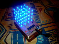
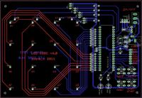
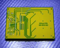
The board was designed in Eagle and milled.
Scheme of the board in Eagle:
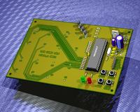
Visualization of the board in graphics overlay 3D (POV-Ray) front / rear
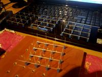
The way to make matrix presented on the base webpage of the project is ideal. You must have a plate (e.g. wooden) with the planned dimensions and drill holes in it (e.g. using a drill 5mm and distances between LEDs 2,5cm when the diameter of LEDs is 5mm). Soldering rather does not cause problems, one layer is about 15 minutes of work.
Programming:
Another advantage of the system is that it has a programming bar. So at any time you can connect the programmer and change the existing code to suit your needs. The programmer used in this project was USBasp. The program was written in C and compiled in Eclipse+Avrdude+WinAvr.
Power supply:
The system can be powered by the alternating voltage in the range of 0-35V, because it has a +5V voltage stabilizer built on the system 7805.
Elements used:
- Atmel AVR Atmega16 + stand
- 64 LEDs (diffusion – blue) 5mm
- 2 LEDs 5mm (red, green)
- resistor 220ohm x 18
- resistor 470ohm x 2
- resistor 10kohm x 5
- transistor BC338 NPN x 4
- capacitor 10uF x 1
- capacitor 1000uF x 1
- ceramic capacitor 0,1uF x 6
- ceramic capacitor 22pF x 2
- crystal oscillator 14.7456 MHz
- 4x micro switch
- power socket
- metal spacers
- rubber bands for distances
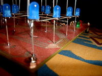
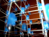
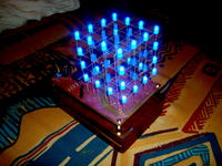
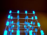
Gallery:
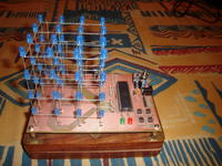
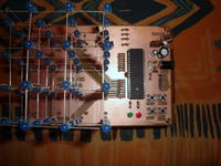
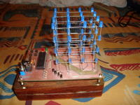
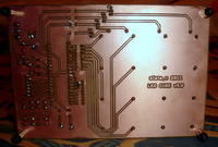
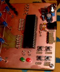
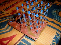
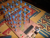
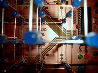
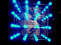
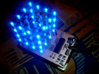
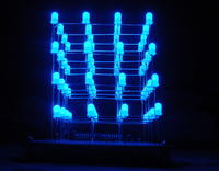
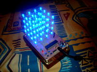
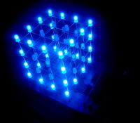
Link to original thread (useful attachment) – LED CUBE 4x4x4 [Atmega16][C]
