Continue to Site

Welcome to EDAboard.com

Welcome to our site! EDAboard.com is an international Electronics Discussion Forum focused on EDA software, circuits, schematics, books, theory, papers, asic, pld, 8051, DSP, Network, RF, Analog Design, PCB, Service Manuals... and a whole lot more! To participate you need to register. Registration is free. Click here to register now.

Lead-acid battery charging circuit

Alireza770717

Junior Member level 2
Joined
Nov 21, 2023
Messages
24
Helped
0
Reputation
0
Reaction score
0
Trophy points
1
Activity points
144
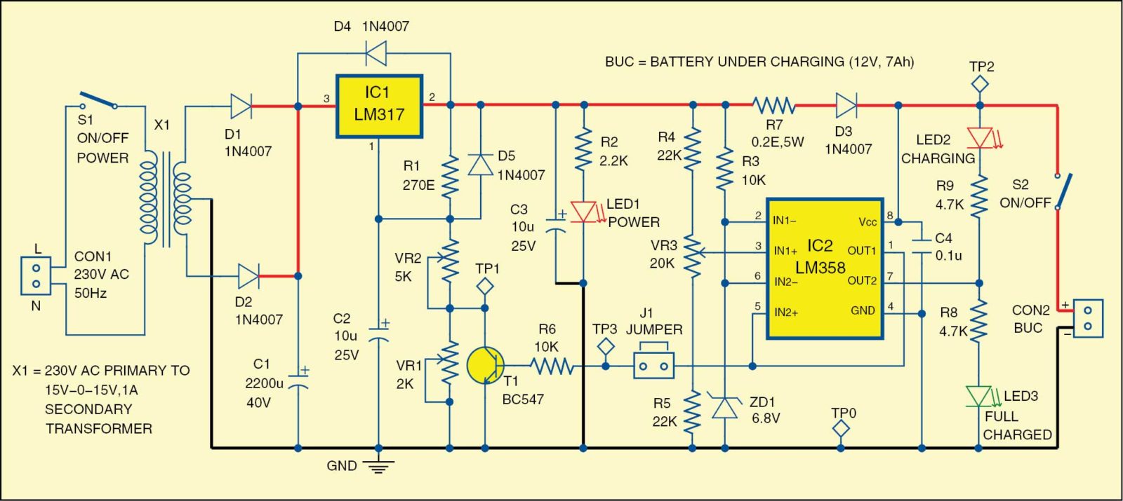
"This schematic is for a lead-acid battery charger circuit. I've set up this circuit, but it's only charging at about 15 milliamps. Can anyone help me troubleshoot this problem? By the way, all component values are according to the schematic, except I used a 13-volt transformer instead of a 15-volt one."

I anticipated that the circuit would output an initial charging current of approximately 400 milliamps, which would subsequently taper off to 100 milliamps as the battery reached a full charge.

F6F_Fig-1.jpg
 
Hi,

there are 3 pots to adjust operating points.
Did you do it? They need to be adjusted.

My guess:
* VR1 and VR2 set the currents for charging and idle
* VR3 sets the end_of_charging voltage

I don´t tink it´s your design. Thus I expect there comes some description along with the schematic. --> use it. And on any questions refer to it. Give a link.

The design needs to care about the high current paths as well as to for the amplifiers not to oscillate. You should have some understand on how to do so.
If you want us to give more detailed help, you need to do soem measurements and give us the values. Like C1 voltage, battery voltage, IC1_pin2, IC2_pin1, IC2_pin7 ...

This is a mature design maybe from 40-50 years ago. Electronics has advanced since then, also the understanding of the battery chemistry.
Thus a modern design would use switch mode technique and dedicated battery charger ICs to reduce part count, to reduce dissipated heat (waste) and to increase accuracy and battery lifetime.

Klaus
Thank you very much. You're sending me a suitable circuit for charging.
 

LaTeX Commands Quick-Menu:

Similar threads

Part and Inventory Search

Welcome to EDABoard.com

Sponsor

Back
Top