Continue to Site

Welcome to EDAboard.com

Welcome to our site! EDAboard.com is an international Electronics Discussion Forum focused on EDA software, circuits, schematics, books, theory, papers, asic, pld, 8051, DSP, Network, RF, Analog Design, PCB, Service Manuals... and a whole lot more! To participate you need to register. Registration is free. Click here to register now.

LCD Inverter Interface

Status
Not open for further replies.

danjurodan

Newbie level 3
Newbie level 3
Joined
Oct 20, 2007
Messages
3
Helped
0
Reputation
0
Reaction score
0
Trophy points
1,281
Activity points
1,299
Dear Professional,

I’m developing a product for my company in R&D area. I want to use a touch panel & LCD Panel to my product.
My PCB using INTEL platform. Single channel LVDS will going through MCH. My question is how I want to interface the inverter into this Intel platform PCB (Highlight with Red area).
Click For Your Perusal
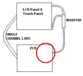
29_1192847525.jpg
 

I think most inverters for the LCD panels is either 12V or 24V input voltage (for larger LCD size) but by looking at your diagram I think it could be 12V. Does the PCB have a 12V output so that you can supply the voltage to the inverter?
 

Thanks for your reply,
I'm using 12V for the supply. My problem is how i want to connect another signal from this inverter to the Intel platform ( chipset @ ic ).Is it connect directly to chipset or going through an IC? I need a reference design schematic for notebook.
 

What signal do you want to connect (on/off, dimming)?
 

Yes, the dimming signal.Nay you help me?Did you have any notebook schematic?
 

Status
Not open for further replies.

Part and Inventory Search

Welcome to EDABoard.com

Sponsor

Back
Top