Continue to Site

Welcome to EDAboard.com

Welcome to our site! EDAboard.com is an international Electronics Discussion Forum focused on EDA software, circuits, schematics, books, theory, papers, asic, pld, 8051, DSP, Network, RF, Analog Design, PCB, Service Manuals... and a whole lot more! To participate you need to register. Registration is free. Click here to register now.

LCD interfacing - configuration code for selecting internal oscillator

Status
Not open for further replies.

venthan

Junior Member level 3
Joined
Jul 23, 2018
Messages
27
Helped
0
Reputation
0
Reaction score
0
Trophy points
1
Activity points
272
Hi Seniors,

I am new to programming. Just starting to learn the coding. I am using PIC16F887 Micro controller. I successfully simulated the program with PROTEUS. Now the problem comes when I trying to implement it in HARDWARE mode.

I want to know the configuration code for selecting internal oscillator. And If possible please explain how to select configuration codes for various micro controllers.

I am using MPLAB Software , Hi tech compiler. Please help me out from this issue.

Thanks in advance,
Koventhan.
 

There is a register in the PIC that selects your oscillator mode. What do you mean " how to select configuration codes for various..."?
 

Dear Barry,

Thanks for your reply. I meant that each micro controller has its own configuration code OR configuration codes are same for all micro controller.

As you said can you give a explanation over the register and possibly an example.
 

RTFM.

The PIC data sheet gives very detailed information on oscillator modes. Just open the data sheet, search for "oscillator mode" and you'll find your information.

Microprocessors are ALL different.
 
Dear Barry,

I have gone through Oscillator module page. As per my understanding to select internal oscillator we must use OSCCON register.

I want to setup a 4MHZ internal Oscillator frequency,

OSCCON = 0x65; // is that the correct way of selecting internal oscillator.

Is this enough OR should I add INTOSC register also.

- - - Updated - - -

Dear Barry,

I have gone through the datasheet and found that in order to select internal oscillator we should configure OSCCON register, I need to Set 4 Mhz Internal oscillator frequency, As per my calculation it comes,

OSCCON = 0x65; //Is that right way to select or Should I add some more register.

Please comment.

Thanks.
 

4 MHz INTOSC is the default power on reset value, don't need to write to OSCCON at all. You need to program CONFIG1 fuse for using HFINTOSC however.

There's no INTOSC register in PIC16F887.

Datasheet Table 4-2 gives a summary of all register settings related to oscillator operation-
 
thanks for your guidance. I have successfully added CONFIG1 and executed with hardware by testing simple led glowing. But while using LCD to interface in hardware mode the output is not coming. But same LCD program is successfully running in simulation.

In case of Interfacing LCD - Is there anything we have to special in Hardware?????

Please guide me....
 

Nothing special. Did you execute the full software reset and initialization sequence for the LCD controller with all specified delays? It's often missed.
 
Yes sir, i have successfully interfaced LCD.
Thanks a lot for your guidance.
 

Hi,

Reading through the thread several times... I still don't know what LCD you are talking about and what interface.
There is a very broad range of LCDs from passive glass with individual segments up to intelligent multi color high resolution displays.
And the interface is similar,
and if there is a display controller: what type

If there already is a proteus simulation you should show us the schematic and your code.

Klaus
 
Dear KlausST,

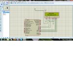
Sorry for the late reply. I am using 16*2 LCD display. After adding CONFIG1 its successfully worked in hardware mode.
lcdscreenshot.jpg.

coding:

Code C - [expand]
1
2
3
4
5
6
7
8
9
10
11
12
13
14
15
16
17
18
19
20
21
22
23
24
25
26
27
28
29
30
31
32
33
34
35
36
37
38
39
40
41
42
43
44
45
46
47
48
49
50
51
52
53
54
55
56
57
58
59
60
61
62
63
64
65
66
67
68
69
70
71
72
73
74
75
76
77
78
79
80
81
82
83
84
85
86
87
88
89
90
91
92
93
94
95
96
97
98
99
100
101
102
103
104
105
106
107
108
109
110
111
112
113
114
115
116
117
118
119
120
121
122
123
124
125
126
127
#include "Includes.h"
 
// Configuration word for PIC16F877
__CONFIG(0X20C5);
 
// Main Function
void main(void)
{ 
//  PORTB = 0x00;               //Assign Port B as Output Port
//  TRISB = 0x00;               //Set PortB as output port
    PORTD = 0x00;
    TRISD = 0x00;
    ANSEL = 0x00;               //Set Digital input
//  OSCCON = 0x65;              //Assign internal oscillator
    InitLCD();                          // Initialize LCD in 4bit mode
    
    ClearLCDScreen();                   // Clear LCD screen
 
while(1)
    {
        WriteCommandToLCD(0x84);           //set address of the first line 4th position
        WriteStringToLCD("Bassoon");    // Write your input on Lcd
        WriteCommandToLCD(0xc2);    //set address of the second line 5th position
        WriteStringToLCD("Technologies");   // Write your input word  on Lcd
        __delay_ms(1000);
    }
}
 
void ToggleEpinOfLCD(void)
{
    LCD_E = 1;                // Give a pulse on E pin
    __delay_us(E_Delay);      // so that LCD can latch the
    LCD_E = 0;                // data from data bus
    __delay_us(E_Delay);    
}
 
 
void WriteCommandToLCD(unsigned char Command)  
{
    LCD_RS = 0;               // It is a command
    
    PORTD &= 0x0F;            // Make Data pins zero
    PORTD |= (Command&0xF0);  // Write Upper nibble of data
    ToggleEpinOfLCD();        // Give pulse on E pin    
    
    PORTD &= 0x0F;            // Make Data pins zero
    PORTD |= ((Command<<4)&0xF0); // Write Lower nibble of data
    ToggleEpinOfLCD();        // Give pulse on E pin
}
 
 
void WriteDataToLCD(char LCDChar)  
{
    LCD_RS = 1;               // It is data
    
    PORTD &= 0x0F;            // Make Data pins zero
    PORTD |= (LCDChar&0xF0);  // Write Upper nibble of data
    ToggleEpinOfLCD();        // Give pulse on E pin    
    
    PORTD &= 0x0F;            // Make Data pins zero
    PORTD |= ((LCDChar<<4)&0xF0); // Write Lower nibble of data
    ToggleEpinOfLCD();        // Give pulse on E pin
}
 
 
void InitLCD(void)
{ 
    // Firstly make all pins output
    LCD_E                = 0;   // E  = 0
    LCD_RS               = 0;   // RS = 0
//  LCD_Data_Bus_D4      = 0;   // Data bus = 0
//  LCD_Data_Bus_D5      = 0;   // Data bus = 0
//  LCD_Data_Bus_D6      = 0;   // Data bus = 0
//  LCD_Data_Bus_D7      = 0;   // Data bus = 0
    LCD_E_Dir            = 0;   // Make Output
    LCD_RS_Dir           = 0;   // Make Output
//  LCD_Data_Bus_Dir_D4  = 0;   // Make Output
//  LCD_Data_Bus_Dir_D5  = 0;   // Make Output
//  LCD_Data_Bus_Dir_D6  = 0;   // Make Output
//  LCD_Data_Bus_Dir_D7  = 0;   // Make Output
 
  ///////////////// Reset process from datasheet //////////////
   __delay_ms(40);
   
    PORTD &= 0x0F;            // Make Data pins zero
    PORTD |= 0x30;            // Write 0x3 value on data bus
    ToggleEpinOfLCD();        // Give pulse on E pin
 
   __delay_ms(6);
   
    PORTD &= 0x0F;            // Make Data pins zero
    PORTD |= 0x30;            // Write 0x3 value on data bus
    ToggleEpinOfLCD();        // Give pulse on E pin
 
   __delay_ms(3);
   
    PORTD &= 0x0F;            // Make Data pins zero
    PORTD |= 0x30;            // Write 0x3 value on data bus
    ToggleEpinOfLCD();        // Give pulse on E pin
 
   __delay_ms(2);
   
    PORTD &= 0x0F;            // Make Data pins zero
    PORTD |= 0x20;            // Write 0x2 value on data bus
    ToggleEpinOfLCD();        // Give pulse on E pin
    
    __delay_ms(2);
  /////////////// Reset Process End ////////////////
    WriteCommandToLCD(0x28);    //function set
    WriteCommandToLCD(0x0c);    //display on,cursor off,blink off
    WriteCommandToLCD(0x01);    //clear display
    WriteCommandToLCD(0x06);    //entry mode, set increment
}
 
 
void WriteStringToLCD(const char *s)
{
    while(*s)
        WriteDataToLCD(*s++);   // print first character on LCD 
}
 
 
void ClearLCDScreen(void)       // Clear the Screen and return cursor to zero position
{
    WriteCommandToLCD(0x01);    // Clear the screen
    __delay_ms(2);              // Delay for cursor to return at zero position
}


Status
Not open for further replies.

Similar threads

Part and Inventory Search

Welcome to EDABoard.com

Sponsor

Back
Top