Continue to Site

Welcome to EDAboard.com

Welcome to our site! EDAboard.com is an international Electronics Discussion Forum focused on EDA software, circuits, schematics, books, theory, papers, asic, pld, 8051, DSP, Network, RF, Analog Design, PCB, Service Manuals... and a whole lot more! To participate you need to register. Registration is free. Click here to register now.

LC Filter Calculations

Status
Not open for further replies.

Dale Gregg

Junior Member level 3
Joined
Jul 23, 2013
Messages
29
Helped
2
Reputation
4
Reaction score
2
Trophy points
3
Location
Leeds, United Kingdom
Activity points
263
Hi,

I designing a H-bridge inverter using a SPWM signal. I'm now trying to calculate the LC low pass filter circuit values. I understand the cut off frequency equation (Fc=1/(2*pi()*sqrt(LC))) but I don't want to just trial and error the values, or is this the normal way? I tried using the inductor voltage eq. V=L(di/dt) transposed as L=V(dt/di) but then realised I dont know what the Vdrop is.

Its probably a stupid question (I'm good at those:oops:) but some advice on how this is normally done would be great as I've been stuck for while.

Dale
 

Hi,

About the operation [Fc = 1/(2*pi*sqrt(LC))], I think it's good because you will find the frequency generate by the LC circuit. I can't tell you more as I begin to learn LC circuit.
 

OK, here goes. This is a very complex task to provide a complete and accurate simulation for various modulation indices, switching frequencies, and load impedances. However, for a first pass, I found an example where someone calculated the spectra for a 100% modulation sinewave.
(https://www.wpi.edu/Pubs/E-project/...-190851/unrestricted/PWM_Techniques_final.pdf)

The purpose of the filter is to reduce the amplitude of the harmonics to a specified maximum level. People normally only look at the first one-to-three large, low order harmonics since usually the high order harmonics are smaller amplitude and also easier to filter. In the Crowley & Lueng paper hypertexted above, figure 9 shows a third harmonic equal to about 15% of the fundamental (160V for the fundamental, 25V for the third harmonic). To reduce the third harmonic to 3% of the fundamental (for a THD of something like 5%, which is about as ugly a waveform as most sensitive circuits can stand) you need a filter that reduces the third harmonic by a factor of 5 (3%/15%). A double-pole filter like the LC reduces the amplitude by a factor of 4 for every octave, so your filter has to have a corner frequency of slightly less than 1.5*fundamental frequency.

Now here's the really nasty part of your LC filter: It's so close to the fundamental frequency (less than an octave), that it will be boosting the fundamental (peaking) instead of having a flat characteristics.

This is a clear case of what one of my friends calls the "Conservation of Misery Principle". You can make the waveform cleaner with a lower frequency filter but it will make your output unstable. You can make the output stable, but your waveform won't be something you want to show your kids.

- - - Updated - - -

I may have not answered your question properly. I answered the question - "What frequency should I choose for a resonant frequency for the filter?" If the question was: "I need to build an LC filter with a resonant frequency of 80 Hz for example. How do I pick the L's and C's?"
The answer to the second question is: (2*pi*80Hz)squared = 1/LC or 252,000 = 1/LC in this example.
Let's try a 1uf capacitor first: L = 1/(252,000*C) = 1/(252,000*1uf) = 3.96H.
OK that inductor is pretty big. Let's pick the L as 396uH instead (1/10000 the size of the the 3.96H we first calculated), now the C is 10000uF. That's a pretty big capacitor. How about something in the middle? How about 39mH and 100uF? or 50 mH and 80uF? or 25mH and 160uF?
Where does the 25mH (or other value) inductor come from? take apart an old power transformer from an old TV (not LCD TV) and start winding turns on it until you get the L you want.
I hope this helps.
 
Last edited:
Regarding capacitors, a large Farad value is associated with:

Longer time constant
Lower frequency
Greater current

As for inductors, a large Henry value is associated with:

Longer time constant
Lower frequency
Smaller current (the exact opposite from capacitor behavior)

As a guide to choosing the proper LC combination, select component values so their reactance at the operating frequency, is the same as the ohmic resistance in the current path.
 
Thank you all for your replies,

I have a much better idea now, I wasn't going to go into that much detail but I will now and the paper you referenced is very good.

In Raymond Mack's book he gives an example of a half bridge smps and a calculation for the output capacitance,

C= 1/(2*pi*200 kHz*8.3mOhm)= 96uF ...8.3mOhm been estimated reactance from "rule of thirds"

the frequency has been doubled for this equation can anyone think of why?

Many thanks
 

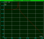
Frequency Response LC Filter.PNG

I've made the filter in Proteus with a 112uH L and a 560uF C with a calculated Fc of 636Hz. Could any one tell me why there's a spike at the knee point?

Regards,

Dale
 

Your graph reveals the resonant frequency of the coil and capacitor.

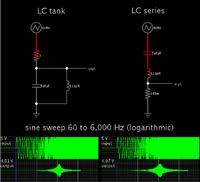
Simulation with sine sweep, showing that an LC circuit is a bandpass filter rather than a low-pass filter.


- - - Updated - - -

The resonant frequency is 636 Hz (occurring close to the geometric midpoint between 60 and 6k Hz).
 
Thanks,

so at Fr Xl=Xc, Z=R causing high voltages across LC. Would the components be under too much stress at this or is this used?

Regards,

Dale

Going by the graph it would unstable?
 
Last edited:

I designing a H-bridge inverter using a SPWM signal. I'm now trying to calculate the LC low pass filter circuit values. I understand the cut off frequency equation (Fc=1/(2*pi()*sqrt(LC))) but I don't want to just trial and error the values, or is this the normal way? I tried using the inductor voltage eq. V=L(di/dt) transposed as L=V(dt/di) but then realised I dont know what the Vdrop is.

Its probably a stupid question (I'm good at those) but some advice on how this is normally done would be great as I've been stuck for while.

Dale
Hi Dale
i can guide you to design your filters for your inverter as well . but it depends on your message signal and your load and feedback path if it is available . and carrier frequency and maximum power rating and format of the load . can you tell me more about them ? then i'll guide you .
Best Wishes
Goldsmith
 
Your graph reveals the resonant frequency of the coil and capacitor.

Simulation with sine sweep, showing that an LC circuit is a bandpass filter rather than a low-pass filter.


- - - Updated - - -

The resonant frequency is 636 Hz (occurring close to the geometric midpoint between 60 and 6k Hz).


Bandpass??? Huh? Dale's figure is flat below the knee and drops off at -40dB/decade above it. Sure looks like a 2-pole lowpass filter to me.

Dale- I had an epiphany about resonance after many years. In school I thought that LC circuits had some mysterious physics behind them that I couldn't understand. You put 1V in and get 100V out (from a circuit with a Q of 100). When I built some really high power output filters for a 180kW AC power supply I realized that at resonance, the filter was shorting the power supply (since Xl and Xc cancelled and all that was left was the tiny R of the inductor). The short circuit current becomes a very high voltage during the 1/2 the cycle (and high current during the other 1/2). It's pretty easy to get 100 times the output voltage of a power supply if you can pull 100 times the rated current from the power supply. So the magic went away - it's like the tooth fairy disappeared...

Regarding your stress question: YEP! If any of your harmonics are close to the resonant frequency, the LC filter will short your output stage (think ugly waveform or even smoke!). We usually put a series R in the LC filter to reduce the Q (down to 1.5 - 3) and decrease the short circuit current. We actually put it in series with the C, so that it's not in series with the load. Sometimes in the literature you'll see something called a "damper" - that's what they mean. The extra R adds AC load to the power supply output so stability is improved, and it doesn't hurt the efficiency very much.
 
Last edited:
Bandpass??? Huh? Dale's figure is flat below the knee and drops off at -40dB/decade above it. Sure looks like a 2-pole lowpass filter to me.

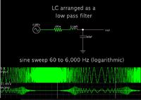
Yes. I changed the sequence of the components to act as a low-pass filter.

The scope trace now shows the charge on the capacitor.


Resonance still plays a part here, although the ohmic resistance needs to be very low in order for it to be obvious.

(My post #7 brings out the resonant action only, for lack of a schematic from the OP.)
 
Hi, Brad- Right.
Now a quick demonstration of Q. XL at resonance (636Hz) = 2*pi*636*L = 0.48 ohms (j ohms but I'll ignore that). The series resistance is 0.2 ohms; Q = .448/.4 = 2.24. With 5 V in you should get 5*2.24 = 11.2V out (your simulation showed 11.5V so that was pretty close). However the 0.2ohm series resistance for a 112uH inductor is pretty darn high, so put in a series R of 0.005 ohm instead. Then add 0.2 to 0.3 ohms in series with the C. You'll get about the same result.

Now you have circuit that has the same Q, but it has the following characteristics:
at frequencies above the knee, the response is more like single pole response because the combination of R and C looks like R (this is bad from a response point of view but it means that the harmonics are driving into a short circuit which is better for your power stage - we also usually add the equivalent of a 56uF -10% of main C - across the RC so we get 2nd order characteristic for the high order harmonics),
the resistive component of the RC dissipates the harmonics as heat instead of returning them into the power stage,
the resistance also helps stabilize the power supply because the resistance causes power to be consumed from the input power (all the rectifier diodes are conducting, the input capacitors are not peak-detecting, etc),
the losses in the system due to the filter are constant (with a large series R, load power is dissipated in the resistor so efficiency and regulation are much worse).
 
Thank you for your replies,

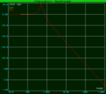
my carrier freq is 3922Hz, fundamental is 50Hz (60Hz max), so I chose a resonant freq of 10 times the fundamental and tried values in a table in excel (now realizing I forgot to square Z). I set the capacitance at 1500uF and then the inductance matching the impedance to the load by
L=C*Z^2 (Z=0.2)
L=60uH
Fc=1/(2*pi*sqrt(L*C))
Fc=531Hz

Frequency Response LC 1.5mF.PNG

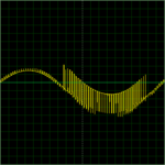
This is the output from my circuit,
LC_OP_scope.PNG

This shows the carrier freq riding on the fundamental, it could be a simulation error though as it shouldn't be there?

I think I'll keep it at this Fr. If I was to bring Fr down to say 60Hz the components would need to be a lot bigger and require more stages. I'm going to try it out tomorrow, would the R in series just need to be near to Z?

Also, I'm a little confused by the calc for Q, where did the .4 come from? Should .448 be .48?
The series resistance is 0.2 ohms; Q = .448/.4 = 2.24.

Many thanks,

Dale
 

Attachments

  • LC_OP.PNG
    LC_OP.PNG
    2.2 KB · Views: 162

my carrier freq is 3922Hz
Hi again
It is a bit low can you increase it till 10 or perhaps 15 KHZ ? then you can set the resonant frequency for about 5 or 6 KHZ so your filter will be cheaper .
For this kind of filter the best responsibility is achieved by zeta=1 . normalize it for that .

Best Wishes
Goldsmith
 
Hi,

I multiplied both my clock and carrier frequency by four to 16MHz and 15.6KHz. The result is the same but at the new frequency so I reckon its a simulation error, I'll find out when I build it. Thanks,
 

Status
Not open for further replies.

Similar threads

Part and Inventory Search

Welcome to EDABoard.com

Sponsor

Back
Top