boylesg
Advanced Member level 4

- Joined
- Jul 15, 2012
- Messages
- 1,023
- Helped
- 5
- Reputation
- 10
- Reaction score
- 6
- Trophy points
- 1,318
- Location
- Epping, Victoria, Australia
- Activity points
- 11,697
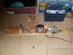
It doesn't look pretty but it should work OK.
The first circuit board contains a voltage pre-regulator which cuts down 38V (3 x car batteries) to 24V on one rail and passes the 38V through on the other rail.
On the second circuit board the 24V rail passes into my LM317 high current voltage regulator, through a salvaged 'heavy duty' rectifier diode with a heat sink. This voltage regulator outputs just over 13V to power the 555 and mosfet gate driver.
I have used a 8 pin IC socket where the 555 timing capacitor would normally go so that I can easily interchange different timing capacitors.
There is also my diagnostic LED. The outputs of both the 555 and mosfet gate driver are soldered to a lead with one of those small two pin socket things at the end - I have many of these from old tv circuit boards. The input of my diagnostic LED, the mosfet gate driver input and the mosfet gate have the female part of those 2 pin sockets. So I can easily change things around and determine any failures.
The 38V rail passes through a 1.0 - 4.7 ohm resistor, which I will be able to submerge under water if necessary, and a 13A fuse.
The last circuit board contains the mosfet itself on a large heat sink with a 12V fan from an old PC power supply and the my snubber array - that is the 9 x 5W series resistors, some of which you can see at the end.
I have used 3 x 250V capacitors in series such that they add up to 68nF with a collective voltage rating of 750V.
Have so far tested the oscillation at my mosfet gate driver IC output and it is all good. Will need to check for oscillation at the mosfet with light globe of some sort next. Perhaps 38V might be just enough to get an ordinary light globe to glow red - I can't use the automtive light globe, as I have been, in this case.

