
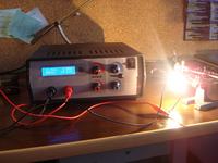
 Assumptions:
- adjustable current limiting; current given up to 5A
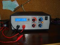
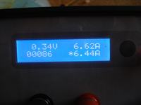
- built-in readable multimeter
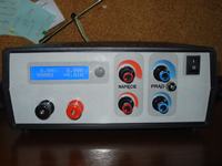
- compact design without unnecessary “air” inside the housing Z-17
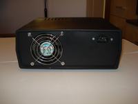
- active cooling without any heat sinks protruding outside the housing
- the whole structure has to be permanent, reliable and safe
The power supply is based on three PCBs
- The first one is the main and auxiliary rectifier board, including filtering capacitors. Additionally, the relay switching the windings of the transformer was placed on it. The PCB is powered by a toroidal transformer 2 x 12V 120VA, with auxiliary winding added to the electronics power supply.
- The second one is the power supply PCB. LM741 amplifiers were used. The path powering the transistors' collectors was cut to adjust it to switching transformer windings in order to minimize the power destroyed on transistors. Two old KD502 were used as final transistors.
- The third board is module consisted of three systems: multimeter, automatic switch of windings and ventilator driver, all with its own supply (bridges, filtration, stabilizers). Automatic switch of windings is a simple WO acting as a comparator. Voltage of switching can be adjusted with the potentiometer. Hysteresis is equal about 4V. Another half of the WO was used to control the ventilator. Any NPN transistor can act as temperature sensor. The activation temperature can also be regulated by the potentiometer. The board is powered by a separate small flooded transformer.
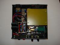
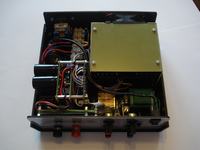
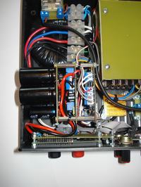
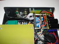
All three boards (in fact, two) were designed so that they can be submitted as a “sandwich” using spacers studs. This allowed to create one slick module, which can be quickly installed or removed from the housing.
Housing and cooling
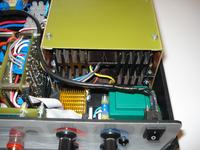
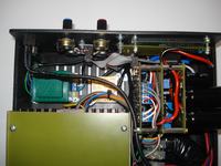
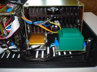
The housing is Z-17. All components inside it are put so there is no free area left at all. Heat sinks do not protrude.
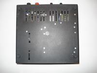
There is a tunnel around the heat sinks, by which the ventilator effectively tread the air through their entire surface. Air is sucked by two holes in the front panel of the housing, dragged through the heat sinks and pushed backwards. Ventilator starts at about 65 degrees Celsius, cooling 10 degrees Celsius at a current of 5A takes about 20-30 seconds. The tunnel is made of soldered pieces of laminate. All screw connections have soldered brass nuts on the inside, making assembly/disassembly very easy and trouble free.
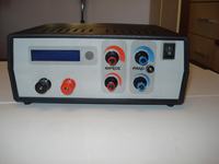
Front panel was designed in Front Designer 3.0, print was laminated.















Link to original thread –
Zasilacz laboratoryjny/warsztatowy na bazie projektu Electronics-Lab