Vermes
Advanced Member level 4

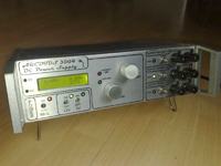
Assumptions:
- the device was to replace all the outlet power supplies
- it was to be equipped with built-in readable measurement module, and meet the requirements on the collection of both characteristics and measurements of parameters in a simple measuring systems
- the possibility of voltage and current limitation adjustment
- the possibility of setting independent voltages so that you always can connect a lot of different devices which need different voltages
- easy to use, reliable, resistant to overload, durable and cheap in construction/possible repair
Realized functions and parameters of the device:
- 3 supply blocks with independent switching additional blocks
- main block adjustable 0-30V 4A with a protection and current limitation
- accurate voltage and current regulation by using 10 rotating potentiometers
- additional blocks 12V 3A and 5V 3A
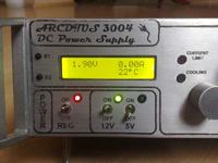
- measurement system for the main block that allows the voltage and current measurement in the main block system
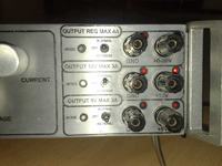
- block of removable/reversible outputs with indication of status and connecting plus to the banana connector
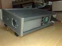
- additional blocks cooling is done passively through the heat sink located at the rear of the device
- main block cooling is based on the system of heat sink and fan
Automatic control of the main block heat sink temperature uses temperature sensor DS18B20 in the heat sink of the main block. You can set the switch on temperature of hysteresis. This feature is realized by measurement module) - 40mm fan that forces air circuit in the housing
- clear division
- aluminum housing
- fully detachable front panel (on few signal/supply connectors) for easy repair or modernization
Elements to be improved/refined:
- adding a fan temperature control system which forces the air circulation
- installation of protective nets on the air outlets
Used systems/modules:
- power supply unit: a typical and well known design with increased filtering capacity (9400uF) and increased power of resistors at the output
- power supply of unchanged voltage: modules put in the attachment on the original thread
- measuring module: Kit AVT2857 in the configuration of the voltmeter with ammeter and thermostat
Design solutions:
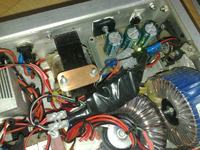
- due to the assumptions, transformers - power supply unit and 12V based on toroidal transformers were used in this project. In 5V power supply transformer of type TI was used.
- measuring block was powered from a converter from a power plug. This solution was dictated by the imposed independence of work of individual modules, in case of short circuit at the additional plug-ins, there is no problem with the work of the measuring module.
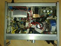
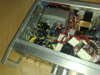
- distribution in the housing is intentional. It can be divided into three parts:
- high voltage AC power supply (right side)
- control, monitoring, parameters reading system (front)
- stabilization, measurements, control and treatment of current and voltage (left)
The system of outputs control was used to make the work with this power supply easy, safe for supplied systems and fast in use.
The device is equipped with a main 230V voltage switch (it switches on the power supply unit, measuring/control apparatus and voltage for two additional, which allow to disconnect them independently from the main block).
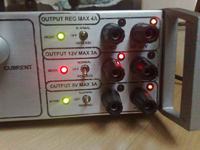
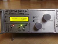
As you can see in the following picture, each output block has:
- switch of on/output polarization
- diode symbolizing NORMAL (green)/REVERSE (red) work
- diodes indicating where is plus – simply near the setting the operation mode of diodes, and lights near the socket where is the positive potential
- banana sockets, where left socket is the mass by default
The mechanical design:
The housing was made of a factory chassis commonly used in all laboratory-measurement industry devices created in the years 70-80-90. The characteristic features are its modularity, the ability to set up multiple devices thanks to the unification of series sizes and special feet-holders. There are several widths and heights in those types of housings. The front wall has two layers, so the decorative (external) panel covers the nuts and bolts on the mounting panel.
Any holes in a shape different than round were finished with files after being pre-treated using a drill (point by point).
The external heat sink was connected with the rear wall of the device, while bridges and stabilizers from additional power supplies were screwed through the housing and heat sink by 3mm dia screws. Most elements were attached to the „floor” by the threaded rod and screws of the same diameter. Isolation of the housing was realized by means of pads cut of a rigid dielectric or insulation tape stuck on the point of contact between the nut and PCB.
All the wiring harness were reduced to minimum. Connection to the network is via a standard computer interface. Weight of the power supply is substantial (approximately 5kg), due to heavy transformers.
Description layer of the front panel was made using thermal transfer method. The gap for the display was supplemented with transparent plexiglass.
Pictures:


Link to original thread (useful attachment) – Zasilacz Laboratoryjno-Warsztatowy Kombajn 3 bloki napięć


