Vermes
Advanced Member level 4

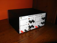
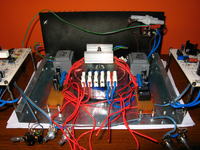
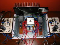
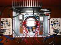
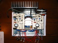
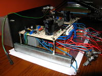
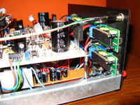
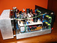
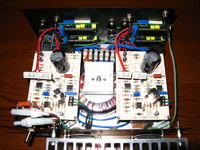
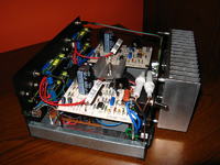
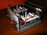
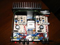
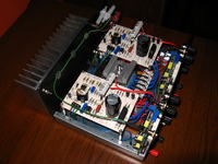
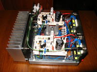
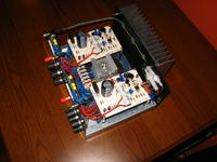
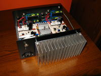
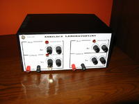
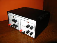
The power supply consists of two separate modules 0-30V 3A. The current and voltage for each of the modules can be controlled roughly as well as accurately. The button on the panel turns on the symmetrical voltage, which means that using only one potentiometer you can regulate the voltage for both modules. Stereo potentiometer is not very accurate, so the voltage difference can be tuned by the potentiometer of the second module responsible for precise adjustment.
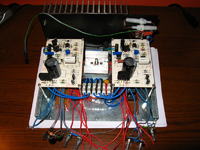
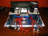
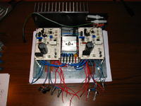
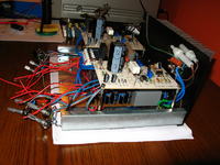
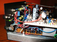
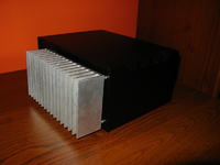
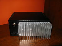
The biggest problem was the mismatch of the modules in the housing. Gretz bridges were too high and one of them interferes with the button. The solution was to reverse the power supplies' PCB 180 degrees. The inscriptions were printed, laminated and elements screwed the front panel to the housing.
The power supply operates correctly. However, some modifications can be made. A good idea is to apply PCB own constructed instead of universal ones. 7-segment displays can be replaced with LCD, controlled from the uC. Measurement of voltage would be made using ADC of Atmega, so you would not need modules that power the 7-segment displays, so there would be more free space in the housing. Additionally, you could apply digital control with measurement of heat sink temperature and the input resistance of the powered system.
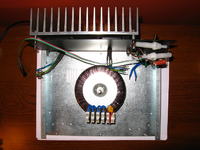
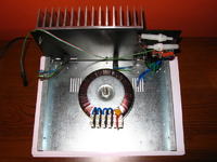
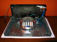

Link to original thread (useful attachment) – Zasilacz laboratoryjny 2 x (0-30 V 3 A) by danzel