Continue to Site

Welcome to EDAboard.com

Welcome to our site! EDAboard.com is an international Electronics Discussion Forum focused on EDA software, circuits, schematics, books, theory, papers, asic, pld, 8051, DSP, Network, RF, Analog Design, PCB, Service Manuals... and a whole lot more! To participate you need to register. Registration is free. Click here to register now.

Laboratory power supply 0-30V 3A, -/+5V

Status
Not open for further replies.

Vermes

Advanced Member level 4
Joined
Aug 2, 2011
Messages
1,163
Helped
0
Reputation
0
Reaction score
0
Trophy points
1,316
Activity points
22,318


Methods:
All boards were made in thermal transfer method after printing on coated paper and imprinting. It is important not to forget to imprint the boards.

Power supply:
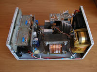
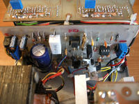
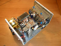
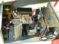
The current regulation is 0,002-3A and tension 0-30V. The transformer used was taken from a rectifier. It had burnt winding. The transformer was disassembled and winded once again at about 24V. Additional auxiliary power supply is a simple symmetrical power supply of a constant voltage equal to -/+5V power from a separate transformer. Its output current is about 1A. It was powered by a separate transformer, which may come from a tape recorder. For a more precise voltage adjustment, an extra potentiometer 1k was added. In the case of current, one coarse works well and does need further adjustment. 2N3055 transistor is on a small radiator, to which there is a possibility of starting a very quiet storm. It was tested for about 30 minutes at a load of about 2A and it was quite warm, but not hot so that a small radiator and a fan together work well.
Measure section:
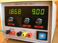
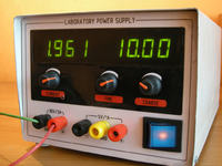
Chosen range of the voltmeter was up to 20V. In the future it may expand to 200V. The ammeter is very accurate, to three decimal places. Its range is 2A. Both meters are powered by 5V transformer, which was taken from a tape recorder and they are separate galvanically.
Housing and front panel:
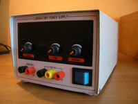
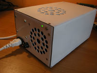
The housing was made at the specific dimensions of sheet one. It was dyed with resistant to scratching spray. The front panel was made before the housing, so that the dimensions were arbitrary. The effect is displayed in the pictures below. The front panel was printed on a colour laser printer, then laminated and glued on double-sided adhesive tape. The mask was made of plexi of 0,5cm thickness. It was milled to the dimensions of the window and darkened by a car foil.
Gallery:


Other projects:

Link to original thread – Zasilacz laboratoryjny 0-30V 3A, -/+5V
 
Last edited:


Status
Not open for further replies.

Similar threads

Part and Inventory Search

Welcome to EDABoard.com

Sponsor

Back
Top