cupoftea
Advanced Member level 6

Hi,
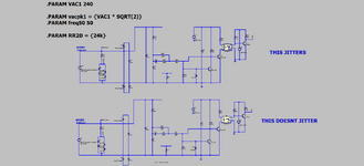
We were experimenting with a mains zero cross circuit as attached.
This is a bog standard, well known mains zero cross circuit, with many imperfections.
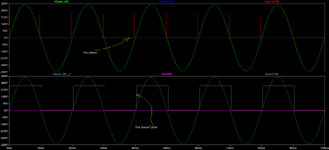
By changing the component values you can choose for the rising edge of the zero cross pulse to come either "just before", or
"just after" the zero cross. (as shown attached).
If you use the "just before" circuit values, then the rising edge of the zero cross pulse is seen to jitter on the scope
(by 'jitter' I mean the rising edge of the zero cross pulse 'scuttles' back and forward over some 15us or so)
If you use the "just after" zero cross circuit values, then there is no jitter seen in the rising edge of the zero cross pulse.
The scope being used is the DS1054Z, and this scope has a known jitter problem.
The thing is, why is the jittering not seen with the circuit where the rising edge of the zero cross pulse comes "just after" the zero cross?
DS1054Z scope jitter problem.
Attached is also the LTspice file of the zero cross ccts.


