Continue to Site

Welcome to EDAboard.com

Welcome to our site! EDAboard.com is an international Electronics Discussion Forum focused on EDA software, circuits, schematics, books, theory, papers, asic, pld, 8051, DSP, Network, RF, Analog Design, PCB, Service Manuals... and a whole lot more! To participate you need to register. Registration is free. Click here to register now.

Issue with Sensorless BLDC motor using controller

Status
Not open for further replies.

RenesasT

Full Member level 2
Full Member level 2
Joined
Mar 11, 2016
Messages
149
Helped
0
Reputation
0
Reaction score
0
Trophy points
16
Activity points
1,330
Hello guys,

I am in big trouble with sensorless BLDC motor project. I am trying to achieve the control of sensorless BLDC motor using microcontroller.

I am using renesas microcontroller. I am able to run the motor but not getting first start.

I am trying by sequence changing with particular delay but its not working.

Once I rotate motor with hand, the motor is starting and then control is through back EMF.

At back EMF stages the motor is working properly. I am worried about my project just because of start up issue.

Please guys help me with the code to start the initial rotations.

Seriously I am worried about my project.

Requesting you all to reply me.
 

Initial acceleration have to be implemented by table of delay values. After that you get angle by measure back EMF.
 

Hello Easyrider83 ,

First of all thanks for your reply.

I am trying in the same way, but the motor is not working properly.

Let us consider two commutation -

1) manual commutation- using delay
2) motor commutation- using motors back emf

At start we need manual commutation. If motor has some load, then it is not starting. Also the current at start even with load or without load is higher.

Please suggest your views.

Awaiting for your valuable reply.
 

If you are using mosfet drivers like ir2110 or similar, you have to increase the value of high side capacitors. They need to keep charge during delayed cycle. Or you should not use 100% PWM on high side. Max 90%.
 

Hello Easyrider83 ,

Very Good Morning to You.

I am not using any drive. I am using ULN buffer IC for driving. My load is fixed. Please let me know the method two drive the motor initially.

If you will describe your method in normal C programming, that would be very beneficial for me or else I have to manage.

Awaiting for your valuable reply.
 

So we are speaking about step motor, not BLDC? Because BLDC will not work from single polarity source. It needs full 3 phases sinwaves.
 

Hello Easyrider83 ,

It is sensorless BLDC with 3 phases.

I am using ULN2003 which has 6 o/p's.

Those 6 o/p's will drive 6 MOSFETS.
 

Hi,

ULN2003 and BLDC....
--> Please show your schematic. And show the ULN signals sequence you use for manual commutation.

Klaus
 

Hello Kluas,

Please find the attached basic image for your reference.

https://obrazki.elektroda.pl/4736170500_1499495414.png

The manual commutation sequence is as follows:

U3 and B2 On, others off
U1 and B1 On, others off
U1 and B3 On, others off
U2 and B3 On, others off
U2 and B1 On, others off
U3 and B1 On, others off


U3 and B2 On, others off
U1 and B1 On, others off
U1 and B3 On, others off
U2 and B3 On, others off
U2 and B1 On, others off
U3 and B1 On, others off


Repetitive...

- - - Updated - - -

Sorry for the keyboard mistake.

The actual manual commutation sequences are

U3 and B2 On, others off
U1 and B2 On, others off
U1 and B3 On, others off
U2 and B3 On, others off
U2 and B1 On, others off
U3 and B1 On, others off

U3 and B2 On, others off
U1 and B2 On, others off
U1 and B3 On, others off
U2 and B3 On, others off
U2 and B1 On, others off
U3 and B1 On, others off

Repetitive....

Awaiting for your reply.
 

The schematic makes no sense at all. ULN2003 is an open collector driver that can't drive MOSFETs without additional circuit elements. A complete schematic would show supply voltage, MOSFET source, drain and gate terminals and their connection to the driver.
 

Hello FvM,

You are right. I have given just basic diagram of sensorless BLDC motor.

My circuit is ok and its working fine. Just I have a doubt in software part. How to start the motor.

I am using delay to push motor. Please let me know weather I am going in right direction or not.

Thanking You in advance.
 

So we'll assume the circuit translates the control signals to respective motor voltage and current.

The sequence is generating correct electrical 60° steps. 30° are possible by powering one and two windings alternatively.

To understand why the motor isn't starting, we need to know the load conditions. They haven't been mentioned yet. Without a static load torque, a slow start sequence would work in any case, initial step period and acceleration have to be chosen according to inertia torque.

There are still open questions. Most BLDC drives are using constant current rather than constant voltage and current controlled PWM circuits to achieve it. Nothing of this kind has been reported for this drive yet.
 

Did you configure the FET drivers as half-H bridge? Then you have to consider high side and low side madness!!

You also need to bother about the dead time; the FET must not appear as a short anytime during the operation.

If you start with a slow speed, the boot strap cap may need to be increased because it may not hold the charge.

Some how your motor is not having the full torque; that means (i) voltage (ii) current (iii) duty cycle is not sufficient. IS IT producing the recommended torque at the full speed?

You can generate dead time in software by pulling down all the outputs to zero between the next pulse but you cannot make level change (for high side drive) in software.

What are the motor's rated power, voltage and current and load?
 

Hello FvM,

There are still open questions. Most BLDC drives are using constant current rather than constant voltage and current controlled PWM circuits to achieve it. Nothing of this kind has been reported for this drive yet.

How to do this?

Please suggest me? I am using trapezoidal way of control. Are you talking about FOC technique?

- - - Updated - - -

Hello c_mitra,

Did you configure the FET drivers as half-H bridge? Then you have to consider high side and low side madness!!

Yes I am taking care of high side and low side. Upper three mosfets are controlled by high and low logic levels and downer mosfets are controlled by PWM.

At a time only two mosfets are active one from upper and other from downer.

You also need to bother about the dead time; the FET must not appear as a short anytime during the operation.

The dead time has been set by software.

What are the motor's rated power, voltage and current and load?

The rated powers are 300W(12V and 25A) and 600W(24V and 25A).

Awaiting for replies.
 

For many, the motor is quite powerful and you need to be careful when you handle high current.

What is the purpose of ULN2003? High side drive signals will not work when you use them.

As your motor is working fine under low load, please use slow accel in the software to bring the motor upto speed. Also note whether the motor is getting very hot (that will suggest wrong timing for the signals).

As you are doing PWM, how many points are used for the sine wave lookup table?
 

Hello c_mitra,

As you are doing PWM, how many points are used for the sine wave lookup table?

I am not getting it.

The ULN2003 IC is acting as a driver for the MOSFETS.

ULN2003 is a negative buffer IC.

The logic is so simple. First push the motor to rotate it for some rotations.

After first few rotations switch control to the back emf from the phases. For this I am using resistor divider and the o/p of resistor divider is given to the ADC i/p of the microcontroller. The zero crossing is giving me the idea about next MOSFETS to be turn ON.

I am sticking at the first time motor rotations. Please help me to get those controls.
 

Your motor will work only with very reduced loads; for proper operation, you need to have a driver with high side and low side. The motor in the present case gets only positive voltage and it never sees the negative side.

In my opinion, you need to reconfigure the whole circuit so that each half bridge is driven with a suitable driver.
 

Seems to be autor doesn't really need any support. Otherwise he will provide more information.
 
  • Like
Reactions: FvM

    FvM

    Points: 2
    Helpful Answer Positive Rating
Hello Easyrider/ c_mitra ,

Good News is that, I am able to drive the motor initially.

Thanks. I am able to drive the motor and drive the motor initially.

Now , What I am facing is, I am not getting torque for the motor. With sensor, my motor reaching upto 20A. But without sensor, it is reaching upto 6A only.

Please suggest the same.

Awaiting your help.
 

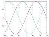
I am putting a graph of three phases with 60 deg steps; you need to turn on and off the upper and lower mosfets as per this drawing.


You are clearly not doing PWM because you will need to have a look up table.

Positive values to the top mosfets and the negative values go to the lower ones.

I am not able to check your connections.
 

Status
Not open for further replies.

Part and Inventory Search

Welcome to EDABoard.com

Sponsor

Back
Top