Continue to Site

Welcome to EDAboard.com

Welcome to our site! EDAboard.com is an international Electronics Discussion Forum focused on EDA software, circuits, schematics, books, theory, papers, asic, pld, 8051, DSP, Network, RF, Analog Design, PCB, Service Manuals... and a whole lot more! To participate you need to register. Registration is free. Click here to register now.

Issue communicating to Honeywell pressure sensor to I2C bus

Status
Not open for further replies.

mrcc

Newbie level 4
Newbie level 4
Joined
Oct 18, 2018
Messages
5
Helped
0
Reputation
0
Reaction score
0
Trophy points
1
Activity points
46
Hi,

I am trying to communicate with the Honeywell pressure sensor, SSCMRNN015PA3A3, via I2C but it seems that it is not replying or not acknowledging the request.

The set up I have is that I am connecting on my USB port, a FTDI cable C232HM-EDHSL-0. With this I am using FTDI's API to send a read to this pressure sensor.

I am driving the pressure sensor with 3.3V with 1k pull ups on both the SCL and SDA lines.
I have also added a 1300pf cap to the SDA line to slow down the rise and fall time, seems that the SCL is also having some offshoots.

I2C waveform3.png

The address for the pressure sensor, according to Honeyell's datasheet, is set as 0x38 which is 0111000 binary.

It seems that the sensor is not pulling down on the SDA line to ACK the Master's request, see oscilloscope output below, SCL is RED and SDA is BLUE:

I2C waveform1.png

Here is a view which includes the Start bit at the beginning:

I2C waveform2.png

My scope have an I2C decoding function and it seems to see the whole sequence:

I2C decoding.png

I am stumped on this problem. I have tried it on more than one sample of the same model of sensor but the same issue.


Anyone have an expertise on either this sensor, the USB cable or I2C?
 

Hi,

I have also added a 1300pf cap to the SDA line to slow down the rise and fall time
I don't recommend this. The timing should be controlled by the bus devices, not by additional capacitors.

It seems that the sensor is not pulling down on the SDA line to ACK the Master's request
When the slave doesn't acknowledge, then the following data is not valid.
You may immediately stop transmission after nACK and start a new try.

For my taste the SDA edges are close to the SCL edges... even with the use of your capacitor...

Klaus
 

Hi Klaus,

For my taste the SDA edges are close to the SCL edges... even with the use of your capacitor...

Do you mean that the SDA edge and SCL edges are too close in my example?

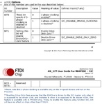
I am commanding via the USB cable's API and there does not seem to be anything I could do other than to change the options for I2C through this API. (not whitout changing the library anyway) I am not quite sure what this option 3-phase-clocking mean:

View attachment 149580

The waveform from the original post is shown when the 3 phase clocking is disabled.


FTDI's API manual is here:

https://www.ftdichip.com/Support/Documents/AppNotes/AN_177_User_Guide_For_LibMPSSE-I2C.pdf


The following is an example of when I enable this 3-phase clock option:

I2C waveform4-3phase-enable.png

Still no positive reply from the sensor though.

Any suggestions?

- - - Updated - - -

The image seem to have lost from my last message regarding the 3-phase clocking.

Here it is again:
I2C cable setting.png
 

Hi,

3phase clocking.
During data transmission the SDA must change only during SCL = HIGH.
No SDA transition allowed at SCL = HIGH, or falling or rising.
SCL falling to SDA change is 5us minimum in standard mode.
SCL falling to SDA change is 10ns minimum in HS mode.
For more details I recommend to read I2C specification.

****

When there is no traffic on the I2C, then the bus should be idle.
I2C idle means that both SCL and SDA are HIGH.
This is not the case in your scope pictures.

I'm not experienced with the FTDI I2C API....but from your scope signals it seems you miss to include I2C_START and I2C_STOP commands.

Klaus
 

Required minimal SDA hold time after SCL falling edge is 0 for I2C. In so far, the timing is correct. You can expect the FTDI I2C API to give correct timing.

- - - Updated - - -

Review Honeywell I2C technical note https://sensing.honeywell.com/i2c-c...sure-sensors-tn-008201-3-en-final-30may12.pdf

The range of available I2C addresses suggests that Honeywell reads default address 0x38 as right adjusted 8-bit value rather than 7-bit value, a popular source of confusion with I2C devices. There's also a certain risk that your device has been shipped with a different I2C address. Worst case I would perform a complete address scan.

- - - Updated - - -

When there is no traffic on the I2C, then the bus should be idle.
I2C idle means that both SCL and SDA are HIGH.
This is not the case in your scope pictures.

I'm not experienced with the FTDI I2C API....but from your scope signals it seems you miss to include I2C_START and I2C_STOP commands.
Start is shown in post #1, third image.
 

The range of available I2C addresses suggests that Honeywell reads default address 0x38 as right adjusted 8-bit value rather than 7-bit value, a popular source of confusion with I2C devices. There's also a certain risk that your device has been shipped with a different I2C address. Worst case I would perform a complete address scan.

So from the scope value this is correct for 0x38?

Can you also explain the difference between 0x38 as a right adjusted 8-bit vs a 7 bit value?
 

Hi Klaus,

When there is no traffic on the I2C, then the bus should be idle. I2C idle means that both SCL and SDA are HIGH.


I have compressed the capture to fit the screen for clarity. The signals are at idle before the I2C signals and after the nACK from the Honeywell sensor.
 

So from the scope value this is correct for 0x38?

Can you also explain the difference between 0x38 as a right adjusted 8-bit vs a 7 bit value?
According to my reading of the Honeywell document, you should send address bits 0011100(RW).
 

Status
Not open for further replies.

Part and Inventory Search

Welcome to EDABoard.com

Sponsor

Back
Top