Continue to Site

Welcome to EDAboard.com

Welcome to our site! EDAboard.com is an international Electronics Discussion Forum focused on EDA software, circuits, schematics, books, theory, papers, asic, pld, 8051, DSP, Network, RF, Analog Design, PCB, Service Manuals... and a whole lot more! To participate you need to register. Registration is free. Click here to register now.

Is this input circuit adequate for a 5 volt IC?

Status
Not open for further replies.

rexlan

Junior Member level 3
Joined
Aug 20, 2006
Messages
31
Helped
0
Reputation
0
Reaction score
0
Trophy points
1,286
Location
USA -- Florida
Activity points
1,547
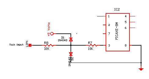
This is the input for my processor. The signal is from my car module and tit is a 12 Volt square wave.

If the chip sees 12 volts it will destroy it. 5.0 Volts is maximum. This is also a high speed signal line so I am not sure if I can buffer it. I also can not load the line


33_1158008190.jpg
 

It won't work because D2 will limit your active high to only one diode drop, or about 0.7 volts.

Instead, use an NPN transistor as follows:
 

The PICAXE input pins can withstand quite a lot, so just reverse the polarity of D2 (anode to GND) and you can remove R7 - that's all ..

Regards,
IanP
 

Thanks all.

I reversed D2 and looked at it on the scope. All it did was clamp the line down and the pulse is gone.

I looked at it as I had it originally and it does work to limit the voltage to 5 volts; however, the signal is now to poor to process. I lost the nice clean rising edge to trigger the PICAXE measurement.

I will try a small FET in place of the transistor. I have some VN10KM parts around.
 

I agree with IanP; D2 is drawn backwards and you don't need R7. If you reversed D2 and it doesn't work there are a number of things that could be wrong.
A. You may have had the diode installed properly and just drew it backwards on the schematic.
B. The diode is bad.
C. Your signal is AC coupled. If this is true the waveform will be badly distorted it the source impedance is high.
D. You may have grounding problems. If you look at the waveform at the pixaxe end with just a resistor across it, does it look clean?
E. What point are you looking at the waveform - at the input or at the pixaxe pin?

How is the code working? You're not abandoning me after you get it working are you? :D

Dennis
 

How is the code working? You're not abandoning me after you get it working are you? :D

Dennis


I posted the code ... works great.

HELL NO .... but you never PM'd me back! :cry:

When I'm done I will make it available to everyone with proper credits as well.

I will go back and check my work again. It may be a ground problem with the scope since I used an external source for the 5 volts. Yes, I had drawn the diode backwards .... but IanP caught it .. not me![/quote]
 

Status
Not open for further replies.

Part and Inventory Search

Welcome to EDABoard.com

Sponsor

Back
Top